


7
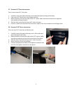
2.7
E
XTERNAL
3.5”
D
EVICE
I
NSTALLATION
There is one external 3.5” drive bay.
1. Carefully remove the plastic drive bay cover and metal plate covering the drive bay.
2. Find a pair of 3.5”drive rails in the hardware kit box.
3. Mount the drive rails onto the sides of the 3.5” device. Make sure the metal portion is angled on
the outside and facing forward.
4. Slide the device into the drive bay until it clicks into place.
5. Connect a small 4-pin connector from the power supply to the 4-pin connector on the floppy drive.
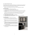
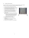
2.8
E
XTERNAL
5.25”
D
EVICE
I
NSTALLATION
There are four 5.25” drive bays and 8 drive rails.
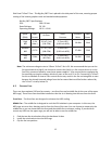
1. Carefully remove the plastic drive bay cover / filter and metal
plate covering the drive bay.
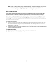
2. Mount the drive rails onto the sides of the 5.25” device. Make
sure the metal portion of the rail faces the front of the drive.
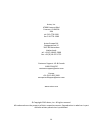
3. Slide the device into the drive bay until it clicks into place.
4. Mount the other devices accordingly.
5. Connect the appropriate Molex or SATA power connector from
the PSU to the power connector on the device.