


connectors to the appropriate headers on your motherboard. You can use
the LED I and LED II connectors as you see fit; as SCSI LED, Message LED,
etc. or any other function supported by your motherboard, expansion cards,
and peripherals.
Connecting the USB Ports
You'll find two 5-pin internal USB connectors (on separate cable sets) attached to
the front USB connectors. Note: If you want to use both front USB connectors
and the 8-in-1 card reader, your motherboard must have at least 3 internal USB
headers.
Here's how to connect the internal USB connector to your motherboard headers:
1. Check the USB pin layout in your motherboard user manual and make sure
it follows this standard pin out:
Pin 1: USB Power - may also be labeled +5V
Pin 2: Negative Signal - may also be labeled P-, D-, USB0-, etc.
Pin 3: Positive Signal - may also be labeled P+, D+, USB0+, etc.
Pin 4: Ground
Pin 5: Ground (sometimes this pin is missing)
Note: Your motherboard's USB pin layout may differ from this common
standard. If you're unsure of your motherboard's layout, please contact
technical support at your motherboard's manufacturer.
2. Connect the 5-pin USB connector so that the red wire is on Pin 1 (Power,
or +5V). The second header may be reversed (Power pin at the opposite
end of the row) so be careful when you plug in both connectors.
Installing 3.5" Devices
There is a 3.5" drive cage inside the case. It can hold 2 external 3.5" drives
and 2 internal drives.
1. Release the cage by pulling the quick release lever towards the rear of the
case. Slide the cage out and put it on a flat, level surface.
2. Mount your floppy drives or other external devices in the top two drive bays.
3. Mount your hard drive or other internal 3.5" devices into the lower drive
bays with the special screws provided. Don't over-tighten. Over-tightening
the screws will harm the vibration and noise reducing ability of the rubber
grommets.
4. Slide the drive cage back into the case and lock it.
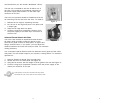
5. For each floppy drive you've installed, find a small 4-pin connector on the
power supply and connect it to the male 4-pin connector on the floppy drive.
3
4
6. For each hard drive or other internal 3.5" device you've installed, find a
large 4-pin peripheral connector on the power supply and connect it to the
male 4-pin connector on the 3.5" device.
Installing 5.25" Devices
1. You'll find four metal plates covering the front openings of the 5.25" drive
bays. Each bay includes a screwless drive rail attached to the front of it.
For each drive bay you wish to use, carefully twist the metal plate back and
forth until it breaks off.
Note: Be careful of the newly exposed metal where the grills were
attached, as these areas are likely to be sharp. Don't break off the plates
covering the drive bays that you're not currently using.
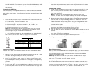
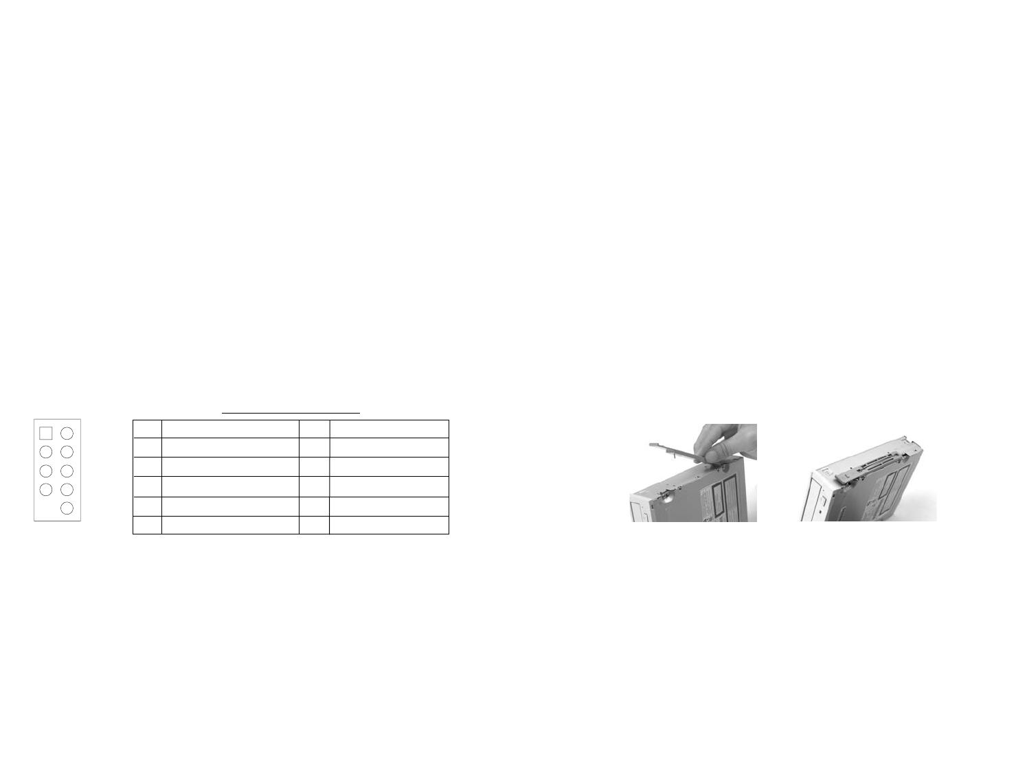
2. Remove the drive rail from the metal plate by gently lifting the release tab
(left end) with one finger and sliding the drive rail to the left. Attach the
drive rail to the right side of the 5.25" device by carefully aligning the drive
rail as illustrated in Figure 1 and pressing along the spring wire from back
to front to seat it as in Figure 2. Make sure the release tab is facing
towards the front plate.
3. On the drive cage, find the black Locking Slider. Open this slider by
squeezing it and sliding it towards the front of the case.
4. Slide the device into the drive bay until you hear a click.
5. Lock the drive into position by sliding the Locking Slider towards the rear of
the case.
6. Connect a large 4-pin peripheral connector from the power supply to the
male 4-pin connector on each device.
7. To install more drives, simply repeat the same procedure.
Attaching the screwless Drive Rails
Data Cable Connection
After you have connected the devices to the power supply, you need to connect
the data cables between the devices and the motherboard. For best data transfer
and cooling performance Antec recommends using a premium rounded data
cable like Antec Cobra Cables.
Useful tip: The cables included with your devices should have a red strip on
side indicating pin number 1. If you use these cables make sure that the red
strip is on pin 1, usually toward the power connector.
Installing the Fan
We've included one low-speed 120mm exhaust fan with this case. This (rear)
fan is mounted with a vibration-absorbing NoiseKiller™ kit, which will allow your
computer to run extremely quietly. In the front of the case, you'll find a mount
for an optional 80mm intake fan. If you decide to add an intake fan, we
Figure 1
Figure 2
12
910
Pin Signal names Pin Signal names
1 USB Power 1 2 USB Power 2
3 Negative Signal 1 4 Negative Signal 2
5 Positive Signal 1 6 Positive Signal 2
7 Ground 1 8 Ground 2
9 Key (No Connection) 10 Empty Pin
Motherboard Pin Layout