


7. LED I, LED II connectors: This case comes with two extra LEDs, marked
LED I, LED II. You may use these LED for various purchases such as SCSI
LED, Message LED, etc.
Connecting the USB Ports
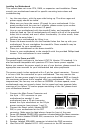
You will find a single 10-pin connector on a cable attached to the front USB
ports. This is an Intel standard connector, which is keyed so that it can't be
accidentally reversed (as long as it's connected to an Intel-standard mother-
board header). Connect the 10-pin connector to your motherboard headers so
that the blocked pin fits over the missing header pin.
Note: Please check your motherboard manual for your USB header pin layout
and make sure it matches the attached table. If it does not match this Intel
standard, please call Antec customer service at (800) 22ANTEC (North America)
or +31 0 (10) 462-2060 (Europe) to buy a USB adapter. This adapter will
allow you to connect the front USB to your motherboard on a pin-by-pin basis.
Installing 5.25" Devices
Your new case features four 5.25" drive bays. Each is covered by a ventilated
metal cover and an EMI Contact plate as one contiguous assembly. To make
installation easier and quicker, we've prepared the top drive bay without the
metal plate. If you'd like to install a 5.25" drive in another bay:
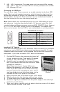
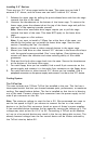
1. Find the EMI Contact plate covering the lower half
of your chosen drive bay. Then bend it 90 degrees
inwards to form a drive support. (See Photo 1).
2. Carefully twist the assembly that covers the upper
half of your chosen drive bay back and forth. When
it breaks off, remove it.
Note: Please watch your fingers. Where you
removed the assembly, you're likely to find sharp
metal. If you don't plan to use certain drive bays,
leave the metal cover assemblies in place. And if
you later decide to cover drive bays again, we've
included two EMI cover plates in the toolbox.
3. Mount two drive rails to the sides of your 5.25" device.
4. Slide the device into the drive bay until you hear a click.
5. To install more drives, simply repeat the same procedure.
6. Connect a large 4-pin connector from the power supply to the male 4-pin
connector on each device.
7. When you're done, carefully push the plastic drive bay covers off the bezel.
Then re-attach the bezel to the case.
4
Photo 1
12
910
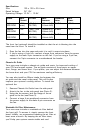
Pin Signal names Pin Signal names
1 USB Power 1 2 USB Power 2
3 Negative Signal 1 4 Negative Signal 2
5 Positive Signal 1 6 Positive Signal 2
7 Ground 1 8 Ground 2
9 Key (No Connection) 10 Empty Pin
Motherboard Pin Layout