


4
To measure the +12V1, +12V2, +5V and +3.3V outputs:
1. Set the measuring dial of your meter to VDC. Choose a maximum measuring range of
+20VDC or higher.
2. To measure the +12V
1 output: Use a 4-pin Molex connector from the power supply and
insert the positive pole (red) to the connector pin with the yellow wire. Insert the negative
(black) to one of the connector pins with a black ground wire.
3. To measure the +12V
2 output: Use the 4-pin +12V CPU Power connector from the power
supply and insert the positive pole (red) to a connector pin with a yellow wire. Insert the
negative (black) to one of the connector pins with a black ground wire.
4. To measure the +5V: Use a 4-pin Molex connector from the power supply and insert the
positive pole (red) to the connector pin with the red wire. Insert the negative (black) to one
of the connector pins with a black ground wire.
5. To measure the +3.3V: Use a Serial ATA connector and a 4-pin Molex connector from the
power supply and carefully touch the positive pole (red) to the tiny pins in the Serial ATA
connector that are connected to the orange wire. Insert the negative (black) pole to one of
the connector pins in the 4-pin Molex connector with a black ground wire. You may
measure the +5V and +12V
1 (red and yellow wires respectively) on the Serial ATA too by
the same method.
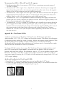
Appendix B — TrueControl II-550:
In addition to the features of TruePower 2.0, TrueControl II-550 features individual,
front-accessible +5V, +3.3V, +12V voltage and fan speed controls. This allows user adjustment
of individual voltages while the system is running, without interrupting system functions. With
this functionality you can stabilize a heavily loaded system, even when overclocking.
Additionally, this functionality allows adjustment of minimum speed of internal power supply
fans and case fans connected to Fan Only connectors.
TrueControl II-550 consists of two parts: The TruePower 2.0 power supply and the control
panel. This special power supply must be connected with the panel in order to function
properly and control the voltages. The adjustment range is ±5% of the specified voltages under
idle mode. Note: The +12V knob on the control panel controls both +12V
1 and +12V2 of
your power supply. By turning the +12V knob you will simultaneously change both +12V
1 and
+12V
2 output readings.
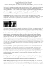
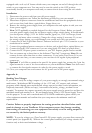
Additional Installation for TrueControl II-550:
1. Install the 5.25" front control panel into your case just like other 5.25" device.
2. Connect the 6-pin white control panel connector (white cable) to the connector behind the
control panel. The installation is completed. (pic 3, pic 4)