


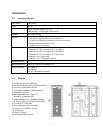
Hardware Installation
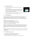
2.1 Setting Up
1.
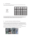
Place the case upright on a flat, stable surface so that the rear panel (power supply and
expansion
slots) is facing you.
2.
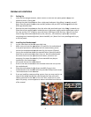
Remove the panel thumbscrews from a side panel and o
Note: Place the panel thumbscrews carefully aside as they are NOT interchangeable with the
HDD cage thumbscrews.
3.
Remove the panel thumbscrews from the other side panel and open it by sliding it towards you.
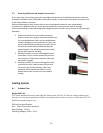
Place the screws carefully aside. Inside the case is the power supply mount at the lower rear of
the case and the 5.25” drive bay area with three HDD cages inside the bays. You will also find
some wiring with
marked connectors (USB, PWR etc.), an installed
containing more hardware (screws, brass standoffs, etc.) Note: Don’t use your fingernail to pry
or lift the panels.
2.2
Installing the Motherboard
1.
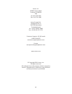
Lay the case down so that the open side is up.
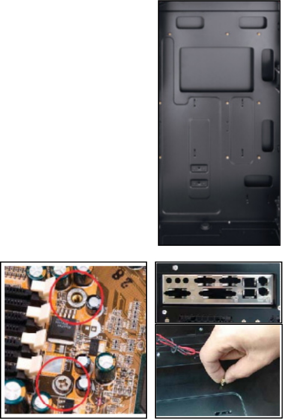
2. Make sure you have the
appropriate I/O panel for the motherboard.
If the panel provided is not suitable for the motherboard, please
contact the motherboard manufacturer for the correct I/O panel.
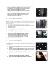
3.
Line up the motherboard with the standoff holes. Determine which
holes line up
and remember where they are. Not all motherboards
will match with all of the provided screw holes, and this is not
necessary for proper functionality. Some standoffs may be pre
installed for your convenience.
4.
Lift up and remove the motherboard.
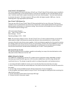
5. Screw
in the brass standoffs to the threaded holes that line up with
the motherboard.
6.
Place the motherboard on the brass standoffs. Screw in the
motherboard to the standoffs with the provided Phillips
7.
The motherboard is now installed.
8.
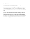
If you are installing a water cooling system,
some
of the tubing outside the case through the hose ports with
rubber grommets on the back of the case. Also, make sure to read
about the pump / reservoir platform feature descr
of the manual.
4
Place the case upright on a flat, stable surface so that the rear panel (power supply and
slots) is facing you.
Remove the panel thumbscrews from a side panel and o
pen it by sliding it towards yourself.
Note: Place the panel thumbscrews carefully aside as they are NOT interchangeable with the
Remove the panel thumbscrews from the other side panel and open it by sliding it towards you.
Place the screws carefully aside. Inside the case is the power supply mount at the lower rear of
the case and the 5.25” drive bay area with three HDD cages inside the bays. You will also find
marked connectors (USB, PWR etc.), an installed
I/O panel and a toolbox
containing more hardware (screws, brass standoffs, etc.) Note: Don’t use your fingernail to pry
Installing the Motherboard
Lay the case down so that the open side is up.
appropriate I/O panel for the motherboard.
If the panel provided is not suitable for the motherboard, please
contact the motherboard manufacturer for the correct I/O panel.
Line up the motherboard with the standoff holes. Determine which
and remember where they are. Not all motherboards
will match with all of the provided screw holes, and this is not
necessary for proper functionality. Some standoffs may be pre
-
installed for your convenience.
Lift up and remove the motherboard.
in the brass standoffs to the threaded holes that line up with
Place the motherboard on the brass standoffs. Screw in the
motherboard to the standoffs with the provided Phillips
-head screws.
The motherboard is now installed.
If you are installing a water cooling system,
then you may need to run
of the tubing outside the case through the hose ports with
rubber grommets on the back of the case. Also, make sure to read
about the pump / reservoir platform feature descr
ibed near the end
Place the case upright on a flat, stable surface so that the rear panel (power supply and
pen it by sliding it towards yourself.
Note: Place the panel thumbscrews carefully aside as they are NOT interchangeable with the
Remove the panel thumbscrews from the other side panel and open it by sliding it towards you.
Place the screws carefully aside. Inside the case is the power supply mount at the lower rear of
the case and the 5.25” drive bay area with three HDD cages inside the bays. You will also find
I/O panel and a toolbox
containing more hardware (screws, brass standoffs, etc.) Note: Don’t use your fingernail to pry