


12
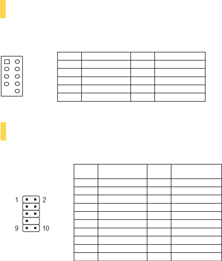
Pin
Signal
Names
Pin
Signal
Names
1
USB
Power
1
2
USB
Power
2
3
Negative
Signal
1
4
Negative
Signal
2
5
Positive
Signal
1
6
Positive
Signal
2
7
Ground
1
8
Ground
2
9
Key
(No
Connection)
10
Empty
Pin
Pin
Signal
Names
(HDA)
Pin
Signal
Names
(AC’97)
1
MIC2
L
1
MIC
In
2
AGND
2
GND
3
MIC2
R
3
MIC
Power
4
AVCC
4
N
C
5
FRO-R
5
Line
Out
(R)
6
MIC2_JD
6
Line
Out
(R)
7
F_IO_SEN
7
N
C
8
Key
(no
pin)
8
Key
(no
pin)
9
FRO-L
9
Line
Out
(L)
10
LINE2_JD
10
Line
Out
(L)
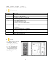
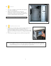
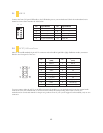
3.1
USB
2.0
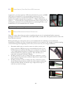
Connect the front I/O panel USB cable to the USB header pin on your motherboard. Check the motherboard user’s
manual to ensure that it matches the table below:
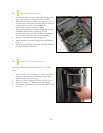
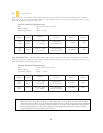
3.2
AC’97
/
HD
A
UDIO
P
ORTS
There is an Intel® standard 10-pin AC’97 connector and an Intel® 10-pin HDA (High Definition Audio) connector
linked to the front panel of the case.
You can connect either the AC’97 or the HDA connector, depending on your motherboard. Locate the internal audio
connectors from your motherboard or sound card and connect the corresponding audio cable. Consult your
motherboard or sound card manual for the pin-out positions. Even if your system supports both standards, only use one
connector.
1 2
9 10