


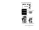
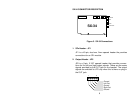
7
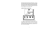
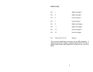
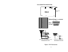
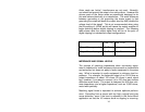
AUX IN (JP9)
Pin 1 Right Aux Input +
Pin 3 Right Aux Input -
Pin 5 Left Aux Input +
Pin 7 Left Aux Input -
Pin 9,11,13,15 No connection
Pin 2,4,6,8,10,12,14,16 Ground
The Auxiliary inputs are balanced inputs, the same as the Line In
and can be used in the same way; as a record source or analog
feed-through to the Line Out.
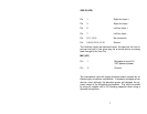
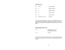
MIC (JP7)
Pin 1 Microphone input (2.5
VDC phantom power
Pin 2 Ground
The microphone input will supply phantom power required by an
Electret type condenser microphone. A dynamic microphone can
also be used, although the phantom power will degrade the dy-
namic range of the microphone somewhat. This can be avoided
by using an adapter with a DC blocking capacitor when using a
dynamic microphone.