


8
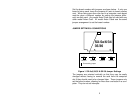
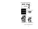
SX-34 CONNECTOR DESCRIPTION
JP5
LINE IN
MIC
SX-34
A
UX
LINE OUT
JP6
JP7 JP4
JP1
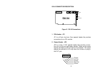
Figure 3. SX-34 Connections
1. SPx Header - JP1
JP1 is a 40-pin, dual-row, 2mm spaced header the provides
connections for an SPx module.
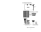
2. Output Header - JP5
JP5 is a 5-pin, 0.100" spaced header that provides connec-
tions for the left and right output signals. These are the same
signals provided by the OUT jack on the bracket. The output
signals are switched to JP5 only when the is there no plug in
the OUT jack.
1
5
Ground
Left Out
Ri
g
ht Out
Ground
Ground