


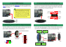
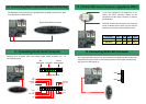
7. Connecting ATX and AGP Pro Power Connector
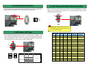
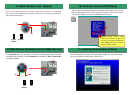
6. Install DIMM Modules
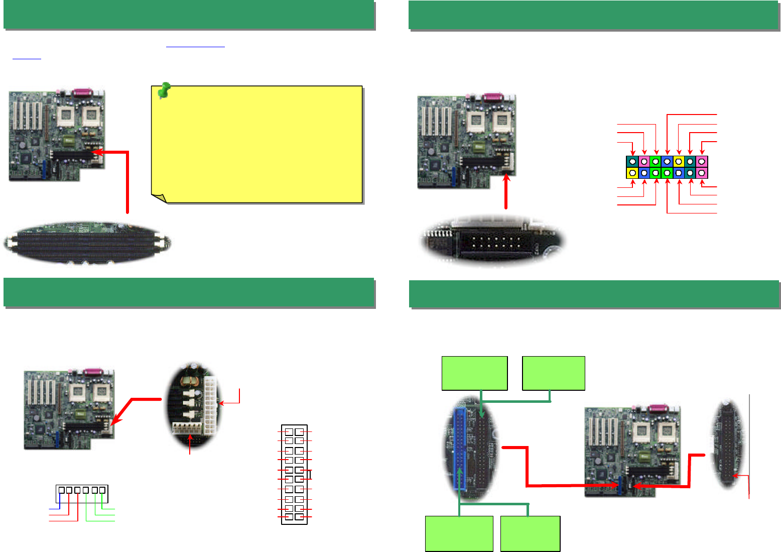
8. Connecting Redundant SPS Connector
9. Connecting IDE & FDD Cable
This motherboard has three 168-pin DIMM sockets
that allow you to install PC100 or
PC133 memory up to 1.5GB. This motherboard
supports not only SDRAM but also VCM
and Registered DRAM.
The DX34 / DX34Plus uses Intel
®
SSI (Server System Infrastructure) type 24-
pin ATX
power connector. The 6-
pin AGP Pro Power connector provides extra +5V and +3.3V
power for AGP Pro VGA card. Make sure you plug in the right direction.
This motherboard implements Redundant SPS connector to provide better expansibility
on superior server. It is feasible to install an additional 337-
watts power supply module
(optional) in a hot-swappable redundant configuration, which enables a fully-
configure
system to continue running even if one power module fails.
Connect 34-pin floppy cable and 40-
pin ATA66 or ATA33 IDE cable to floppy connector
FDC and IDE connector IDE1, IDE2
. Pin1 of cable is normally marked with red color. Be
careful of the pin1 orientation. Wrong orientation may cause system damage.
DIMM 3
DIMM 2
DIMM 1
Tip: The driving capability of new generation
chipset is limited due to the lack of a memory
buffer (to improve performance). This makes
DRAM chip count an important factor to take
into consideration when you install DIMMs.
Unfortunately, there is no way that the BIOS
can identify the correct chip count, you need
to calculate the chip count by yourself.
24-pin ATX Power connector
AGP Pro Power
Connector
+5V
+3.3V
+3.3V
GND
GND
GND
16
1
2
14
13
PS 1 Fail
I
2
C CLK
Present 1
Fan 3 Fail
Fan 1 Fail
PS 2 Fail
PS_ON
PS 3 Fail
Fan 2 Fail
Present 2
5VSB
Present 3
I
2
CDA
GND
IDE2 (Secondary)
IDE1 (Primary)
Primary
Master (1st)
Primary
Slave (2nd)
Secondary
Slave (4th)
Secondary
Master (3rd)
FDD
Connector
ATA/66 IDE
Connector
Pin 1
1
20
19
13
+5V
+5V
-5v
COM
COM
COM
PS-ON
COM
-12V
+3.3V
+12V
5VSB
PWR OK
COM
+5V
COM
+5V
COM
+3.3V
+3.3V