


150/175kw Modular PDU Installation22
Regulatory Agency Approval
This equipment has been tested and found to comply with the limits for a Class A digital device,
pursuant to Part 15 of the FCC and ICES-003 Rules. These limits are designed to provide reasonable
protection against harmful interference when the equipment is operated in a commercial environment.
This equipment generates, uses, and can radiate radio frequency energy and, if not installed and used in
accordance with the Installation Guide, may cause harmful interference to radio communications.
Operation of this equipment in a residential area is likely to cause harmful interference, in which case the
user will be required to correct the interference at his own expense.
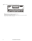
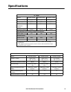
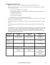
Table for 30°C
ambient/4CCC
PDPM150G6F
480:208
PDPM150L6F
600:208
PDPM175G6H
480:415
Mains Input Φ Cu: 4/0 AWG
A1: 300kcmil
75°C conductor minimum
Cu only: 3/0 AWG
90°C conductor minimum
Cu: 300kcmil
Al: 400kcmil
75°C conductor minimum
Equipment
Grounding Conductor
(EGC)
Cu: 4 AWG
A1: 2 AWG
Cu: 6 AWG Cu: 4 AWG
Al: 2 AWG
Grounding Electrode
Conductor (GEC)
Cu: 2 AWG
A1: 1/0 AWG
Cu: 2 AWG Cu: 2 AWG
Al: 1/0 AWG
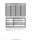
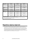
Output Supplied with Power Distribution Modules
Subfeed Output Cu: (2) 250kcmil Φ and N,
3 AWG EGC, GEC not
required.
Al: (2) 350 kcmil Φ and N,
1 AWG EGC, GEC not
required.
90°C conductor minimum
Cu: (2) 250kcmil Φ and N,
3 AWG EGC, GEC not
required.
Al: (2) 350 kcmil Φ and N,
1 AWG EGC, GEC not
required.
90°C conductor minimum
Cu: (2) 2/0 AWG Φ and N,
4 AWG EGC, GEC not
required.
Al: (2) 3/0 AWG Φ and N,
2 AWG EGC, GEC not
required.
75°C conductor minimum
Φ = phase, N = neutral
(2) = two conductors per phase and neutral (when neutral is required)
Subfeed is required to have two conductors per phase & N for full output due to limited wire bend space
Cu= Copper conductors, Al= Aluminum conductors
CCC = Current Carrying Conductor