


Smart-UPS RT 2400/3000 VA Tower/Rack-Mount UPS User Manual 17
Troubleshooting
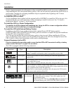
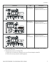
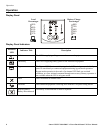
Fault and Overload LEDs illuminated and UPS emits a sustained alarm tone (Refer to “Display Panel
Indicators” on page 8.)
The UPS has ceased sending power to
connected equipment.
The connected equipment exceeds the specified “maximum load” as defined
in Specifications on the APC Web site, www.apc.com.
Disconnect nonessential equipment from the UPS to eliminate the overload
condition.
Press the button, then the button to restore power to connected
equipment.
The Replace Battery/Battery Disconnected LED is illuminated (Refer to “Display Panel Indicators” on page 8.)
Battery is disconnected.
flashes and a short beep is emitted
every two seconds to indicate the
battery is disconnected.
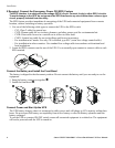
Check that the battery connectors are fully engaged.
Weak battery. Allow the battery to recharge for 24 hours and perform a self-test. If the
problem persists after recharging, replace the battery.
Failure of a battery self-test.
flashes and a short beep is emitted
for one minute. The UPS repeats the
alarm every five hours.
Allow the battery to recharge for 24 hours. Perform the self-test procedure to
confirm the replace battery condition. The alarm stops and the LED clears if
the battery passes the self-test.
If the battery fails again, it must be replaced. UPS output is maintained
during the self-test.
There is no utility power
There is no utility power and the UPS is
off.
Use the cold start feature to supply power to the connected equipment from
the UPS battery.
Press the button for one second and release. The UPS will beep briefly.
Press and hold the button again for about three seconds. The unit will
emit two beeps. Release the button during the second beep.
UPS operates On Battery although line voltage exists
Your system is experiencing very high,
low, or distorted line voltage.
The generator is not correctly sized.
Move the UPS to a different outlet on a different circuit: Inadequately sized
generators may distort the voltage. Test the input voltage with the utility
voltage display. Refer to “Utility Voltage Measurement” on page 9 for
additional information. Contact a qualified electrician to correct the building
wiring.
Diagnostic utility voltage (Refer to “Utility Voltage Measurement” on page 9.)
All five LEDs are illuminated. The line voltage is extremely high and should be checked by an electrician.
Problem and/or Possible Cause Solution