


Environmental Manager: Main Module
13
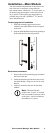
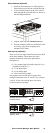
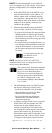
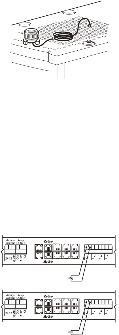
Alarm beacon (optional)
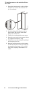
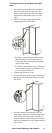
1. Install the alarm beacon in a visible position
either on the roof of the rack or inside the rack.
2. If you install the beacon on the roof, route its
cable through the provided holes, as shown in
the following illustration.
3. Plug the cable into the Alarm Beacon port.
4. You can extend the cable to a maximum of 100
m (330 ft), using RJ-45 couplings and
standard CAT5 cables.
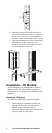
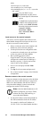
User inputs (optional)
There are four user input connection points provided
on the Main Module. These inputs use screw
terminal connections. Each may optionally be
configured as:
• 5 V dry contact input (Normally Open [N.O.] or
Normally Closed [N.C.])
• 0–5 Vdc digital input
• 0–5 Vdc analog input
• 4–20 mA current loop input
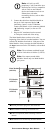
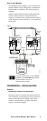
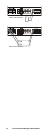
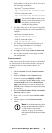
The graphics below and on the next page show
example connections for N.O. and N.C. dry contacts,
2-wire 4–20 mA current loop input, and 4-wire
4–20 mA current loop input.
aem0061a
User Inputs
++
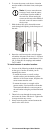
aem0065a
Normally Open (N.O.) Contact
Closed for Alarm
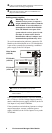
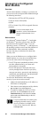
User Inputs
++
aem0066a
Normally Closed (N.C.) Contact
Open for Alarm