


6
Installation and Operation Manual
Specifications
Installation
1. Turn off all power supplying this equipment before working on or inside
equipment.
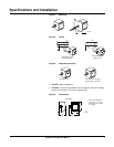
2. For mounting, see Figure 1.
3. Confirm SPD is rated for your system by comparing voltage
measurements to the Line Voltage (L-L, L-N) on the product label.
4. Confirm the black wires are connected to line wires, the white wire to the
neutral wire and green wire to ground (see Figure 2). For the single-
phase, 120/240 3-wire application, connect one of the SPD black wires
to L1 and the other black wire to L2. For the single phase, 120 2-wire
application, connect both SPD black wires to the same line.
5. Twist conductors 1/2 turn or more for every 12 inches of length.
6. Keep conductor length as short as possible with no sharp bends.
7. Do not loop or coil wires.
8. Use on solidly grounded systems only.
Table 1: Voltage Rating
Model Voltage
Peak Surge Current
(Rating per Phase)
Mounting Protection
L-N L-G
PMP1XR-B 120/240 V~ 25 kA 25 kA Side Nipple Surge + Overload
Table 2: General Specifications
1
1
Contains no serviceable parts
System Voltage 120/240 V~
Maximum Continuous Operating Voltage
(MCOV)
150 V~ L-N, 300 V~ L-L
Short Circuit Current Rating
2
2
Suitable for use on a circuit capable of delivering not more than 25 kA rms symmetrical Am-
peres.
25 kA
Nominal Discharge Current (I
n
) 10 kA (L1-N, L1-G, L2-N, L2-G)
Voltage Protection Rating (VPR) 700 V (L1-N, L1-G, L2-N), 800 V (L2-G)
Enclosure Rating and Housing Dimensions Type 4X (see Figure 4)
Product Weight 1.8 lbs (0.9 kg)
Connection Method Parallel, 12 AWG Solid Wire
Thermal Fusing Yes
Operating Temperature -40°F to +160°F (-40°C to +70°C)
Operating Frequency 50/60 Hz
Diagnostics Green Status LED per line
Product Standards
UL 1449—3rd Edition, CSA C22.2 No. 8-
M1986, CSA C233.1-87 and CE
Product Rating Type 1 Surge Protective Device (SPD)
Specifications and Installation