


Installation and Operation Manual 7
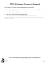
• LED ON = Normal Operation
• LED OFF = Check circuit breakers and connections. Verify line voltage
at point of connection; if all correct, replace SPD.
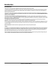
Figure 1: Mounting
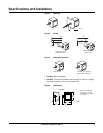
Figure 2: Wiring
Figure 3: Diagnostic Operation
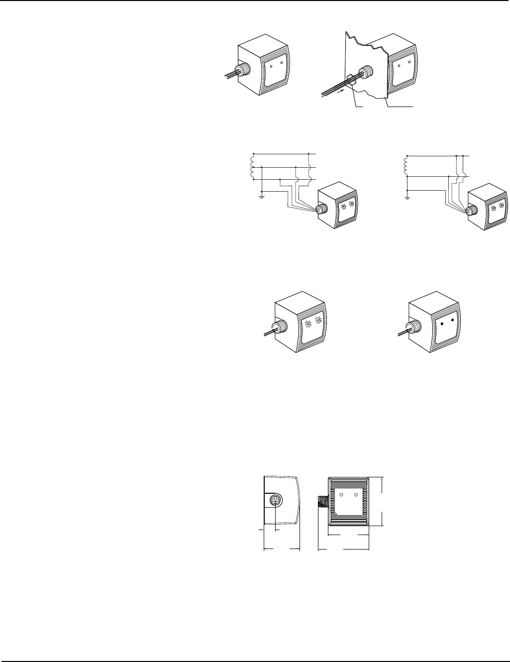
Figure 4: Dimensions
Panel
Nut
Black
Green
Black
White
L1
N
L2
Green
Black
White
L
N
Single-phase 2-wire
(+GND) 120 V~
Single-phase 3-wire
(+GND) 120/240 V~
LED OFF = Loss of Surge
Suppression L1 and/or L2
LED ON = OK
3.75
[95]
3.60
[91]
3.00
[76]
0.87
[22]
2.67
[68]
Side Nipple
in.
[mm].
NOTE: Knockout trade
size is 0.5 in. (13 mm).
Actual hole size is 0.875
in. (22 mm).
Specifications and Installation