


14
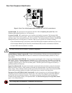
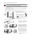
1. Make sure the main circuit breaker , located on the rear
panel, is in the OFF position.
2. Select the appropriate wire size and connectors, according to
local codes. For most applications, #10 AWG (5 sq. mm) wire
should be sufficient.
3. Remove the input wiring access door by unscrewing the single
screw that holds the access panels in place. The input wiring
terminal is located on the rear panel of the Symmetra RM.
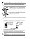
4. Use a screwdriver or any hard object to detach the circular
knockout in the wire input plate . You may need to use pliers
to fully detach the knockout.
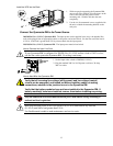
5. Feed the wire cable through the hole on the wire input plate.
Using a threaded lock nut, fasten the plate to the selected cable
or conduit connector.
6. Use a knife to strip off the plastic on the end of the cable to
expose the copper wire. Strip all three wires.
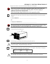
7. Use a flat head screwdriver to connect the wires to the terminal
block . Loosen the screw, then feed the copper wire into the
terminal block and tighten the screw. Connect the protective
earth ground to the terminal block at the position marked with
the ground symbol. Connect the three wires.
8. Reconnect the wire input plate. Align the plate, position it into
the grooves and slide it to the left.
9. Inspect the connections and location of the excess wires before
installing the access door.
10. Replace the access door and fasten with the screw (removed in
step 3).
Once the electrician is finishing wiring the unit, complete the checklist in Appendix A: Electrical Wiring
Checklist, page 17, for verification.
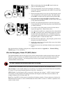
Wire the Emergency Power Off (EPO) Switch
The Symmetra RM provides an emergency power switch connection that controls electrical power to the unit.
When this switch is turned on (or enabled), electrical power to the unit is turned off and the system will not
switch to on-battery operation. You must physically reset the system enable switch on the front of the
Symmetra RM to restart the unit.
Use only a qualified electrician to install the EPO wiring.
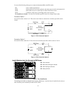
The EPO circuit is considered a Class 2 (UL and CSA standards) and SELV (IEC standard) circuit.
Class 2 Circuit: Used in North America by UL and CSA. It is defined in the National Electrical Code (NFPA
70, Article 725) and in the Canadian Electrical Code (C22.1, Section 16).
SELV Circuit: Used in Europe by IEC; acronym for “safety extra low voltage.” A SELV circuit is isolated
from primary circuitry through an isolating transformer and designed so that under normal conditions, the
voltage is limited to 42.4 V peak or 60 V dc.
Both Class 2 and SELV circuits must be isolated from all primary circuitry. Do not connect any circuit to the
EPO terminal block unless it can be confirmed that the circuit is SELV or Class 2. If there is a question, use a
contact closure switch.