


Operation Manual Universal Transfer Switch UTS6 UTS6H UTS6BI UTS10BI10
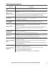
UPS Power Rating
Once the BACKUP2 SOURCE TYPE has been selected, that source type will
appear in the power rating display message. Use the down/up arrow keys to set the
correct power rating for the backup2 power source connected to the UTS.
There are three levels for rapid rating increment changes. Press and hold the down or
up arrow key to adjust the power rating and to move through the three levels described here. To revert back to level 1
release the down arrow key then press and hold the down arrow key.
Level 1 increases or decreases the rating by 5 Watts.
Level 2 increases or decreases the rating by 10 Watts.
Level 3 increases or decreases the rating by 100 Watts.
UPS Surge Overload Time
Once the BACKUP2 SOURCE TYPE has been selected, that source type will
appear in the surge overload time display message. Use the down/up arrow keys to
set the desired ALM response time.
When power output exceeds the pre-set power rating for the Backup21 Source (see
UPS Power Rating above), this feature determines the time it will take for ALM to respond and activate load shedding
process.
Low UPS surge overload time settings decrease the possibility of a generator overload condition while increasing the
possibility that ALM will activate load shedding.
High UPS surge overload time settings increase the possibility of a generator overload condition while decreasing the
possibility the ALM will activate load shedding.
Reset to Factory Default
Use the down/up arrow keys to select YES. This will reset all configurable
parameters to the factory default settings.
Selecting YES will also start the UTS Setup Wizard described in the Site Preparation
and Installation Guide supplied with this unit.
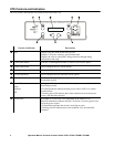
Circuit Status Verification
The status of each circuit on the UTS can be viewed by pressing the Circuit Status button located on the front of the UTS.
To navigate through the circuits, press the Circuit Status button after viewing the status of each circuit.
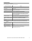
CK1SRC (circuit1 source) indicates the power source (utility power), plus the status of
circuit1: number of Amps, number of kWh, and number of Watts.
Circuit Configuration and Setup
Circuit setup
Press the Circuit Setup button located on the front of the UTS to enter circuit setup mode and to navigate through the
circuit setup options. Circuit setup begins with circuit 1 and proceeds through all of the configuration options for circuit 1
before moving on to circuit 2. The same is true for circuit 2, then circuit 3 and so on.
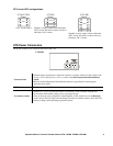
Use the down/up arrow buttons to navigate through the configuration options and to change values displayed on the LCD.
Note: The settings and values selected will change immediately after an arrow button is pressed.
The LCD will revert back to the starting display message after 30 seconds with no activity.
To configure a specific circuit, press the Circuit Status button until the display shows the desired circuit, then press the
Circuit Setup button. The LCD will display the first setup option for the selected circuit.
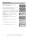
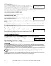
UPS POWER RATING:
0-1800 WATTS
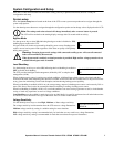
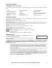
UPS SRGE OVRLD TIME:
0-60 SEC
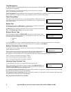
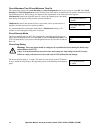
RESET TO DEFAULT:
NO
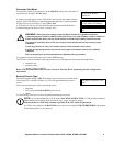
CK1SRC: UTILITY AMP: 1
KWH: 2:35 WATTS: 120