


Operation Manual Universal Transfer Switch UTS6 UTS6H UTS6BI UTS10BI6
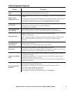
System Status Verification
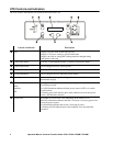
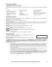
The UTS system status and the status of up to three power sources can be viewed by pressing the System Status button
located on the front of the UTS. To navigate through the system status menus, press the System Status button after
viewing the information on the LCD.
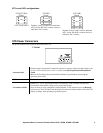
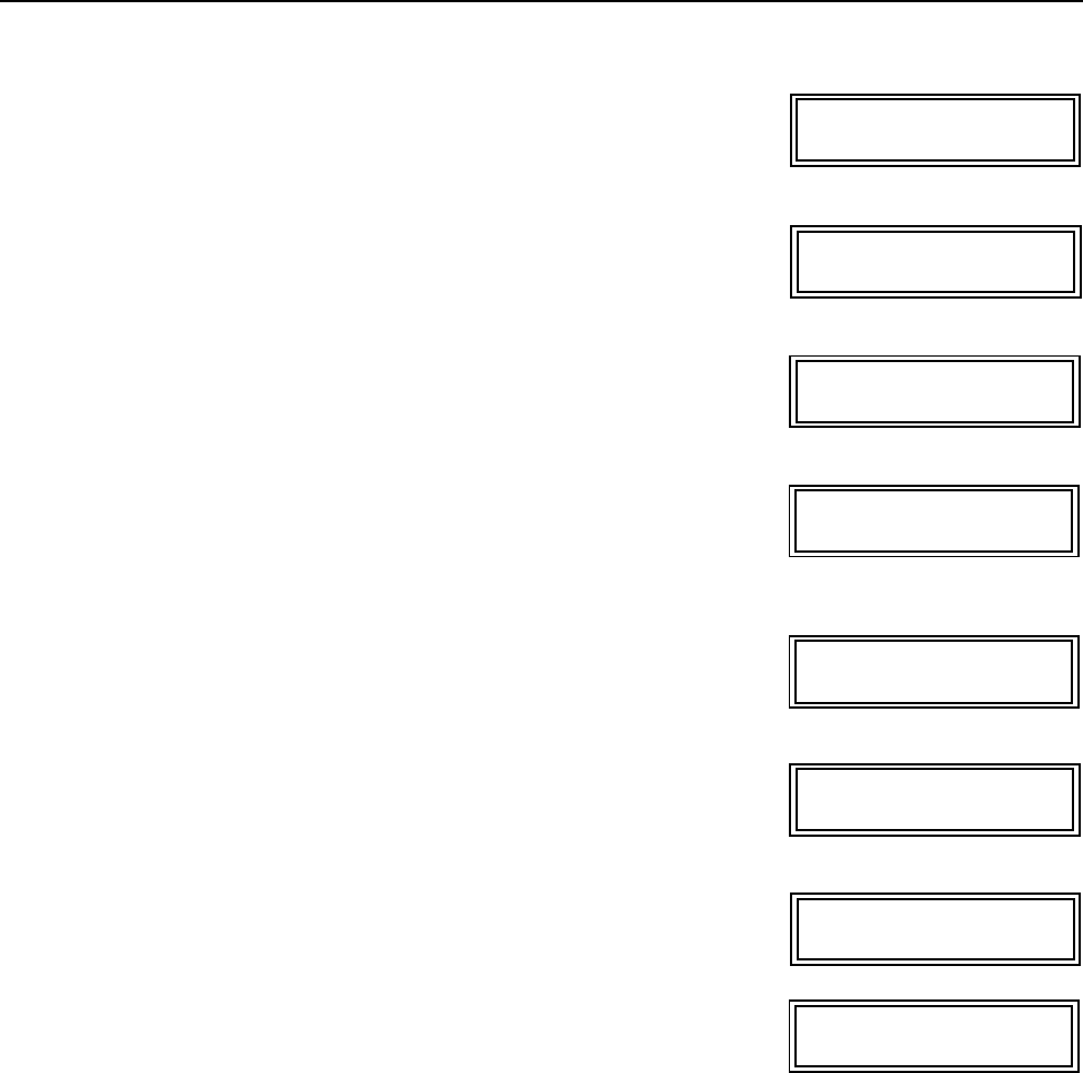
LCD displays the input voltages from the UTILITY through the main
load center for PHASE1 and PHASE2.
LCD displays the SYSTEM LOAD (total power), that is being drawn through the
UTS AND the power drawn by each phase - PH1 and PH2
This information provides verification that the phases are balanced.
LCD displays the BACKUP1 source voltages for GEN PHASE1 and GEN PHASE2.
The UTS6H is intended for use with a single phase, 120 V generator. GEN PHASE1
and GEN PHASE2 will display identical voltage measurements.
LCD displays the BACKUP1 source power outputs for GEN PHASE1
and GEN PHASE2.
For power measurements: phase1 will display the power outputs of circuits 1, 3, 5.
Phase2 will display power outputs for circuits 2, 4, 6.
LCD displays the UPS VOLTAGE and UPS LOAD for the BACKUP2
source (normally a UPS).
LCD displays the MODEL# (model number), and SN# (serial number)
of the UTS.
LCD displays the FW VER (firmware version) installed in the UTS.
LCD displays the MFG DATE (date of manufacture) for the UTS.
UTILITY PHASE1: 120V
UTILITY PHASE2: 120V
SYSTEM LOAD: 2400W
PH1: 1050W PH2: 1350W
GEN PHASE1: 117V
GEN PHASE2: 118V
GEN PHASE1: 480W
GEN PHASE2: 750W
UPS VOLTAGE: 120V
UPS POWER: 200W
MODEL#: UTS10BI
SN#: JB06008004272
UTS FW VER: 1
UI FW VER: 1
MFG DATE: xx/xx/xxxx