


5
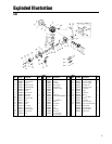
Mounting the Engine
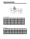
Make sure the engine is mounted on the aircraft using
aircraft grade plywood that’s at least 6mm in thickness
for the G26 engine, and 10mm in thickness for the G38
through GT80 twin, or a mount of equivalent strength.
Make sure it’s firmly mounted with 4 bolts.
1. Be sure to set flat washers or a metal plate on the
reverse side of the mount to prevent the bolts from sink-
ing into the mount. Periodically check the engine mount
for loose bolts.
2. Since the engine is equipped with a floatless carbure-
tor with a diaphragm pump, the direction of the cylinder
and position of the fuel tank can be freely selected.
3. If the engine is mounted on a shock (rubber) mount
placed between the engine and the firewall for anti-vibra-
tion, check the hardness of the rubber, making sure it’s
not too soft, in order to avoid excessive vibration during
engine operating rpms. It’s suggested you note carefully
if the engine is vibrating at idle as excessive vibration
can result in erratic engine operation due to overflow at
the carburetor.
4. It is suggested you coat the bolts for the muffler with
threadlock when mounting the muffler to the engine.
Break-In
No specific break-in is required. The engine is gradually
broken-in as it is used, and the output power increases
gradually as the engine breaks in.
Starting the Engine—Aircraft
Before attempting to start the engine, be sure to read
through all the steps for starting the engine as outlined
below:
Zenoah engines are equipped with the ultra compact
C.D.I. type flywheel magneto ignition system and should
be started according to the following procedure:
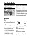
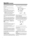
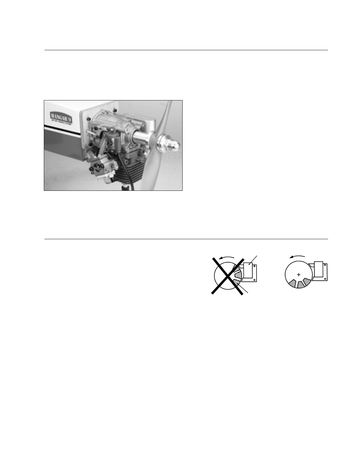
Note: The magneto system is timed in such a
way that when the compression stroke starts
(refer to Figure 1-A) sparks are never produced
on the spark plug, no matter how fast the pro-
peller is flipped. The correct starting procedure
is to quickly flip the propeller when the edge of
the magnet on the rotor is approaching the coil
(Figure 1-B). This means that the propeller
should be quickly flipped at about 90 degrees
in crank angle before the compression stroke is
about to start.
1. Make sure the spark (glow) plug(s) are installed and
tightened. Check the condition of the plug cap for cracks
or breaks.
2. Be sure the propeller is properly secured.
3. Make sure the fuel tank line(s) are properly connected.
The main line should be connected to the carburetor
spray bar.
4. Be certain the mufflers are installed properly.
5. Fill the fuel tank.
6. Choke the engine and turn the propeller through a
few times until the fuel appears at the carburetor.
7. Set the throttle valve at the idle position or at the
position slightly open from idle.
Fig 1-A
Coil
Magnet
Fig 1-B
Operation