


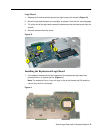

Xserve Logic Board with Processor/Heatsink -
10
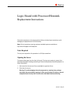
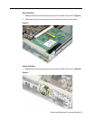
2. Install the replacement logic board in the bottom housing, making sure the board fits
over the four mounting pegs on the chassis floor.
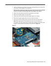
Warning: When replacing the logic board, make sure the ports and the identifier
button on the back of the board align with the openings in the chassis.
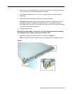
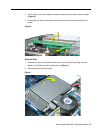
3. Tighten the thumb screw that secures the logic board to the chassis.
4. Reconnect the power supply to the logic board.
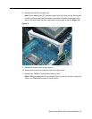
5. Tighten the thumb screw that secures the power supply to the chassis.
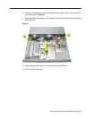
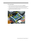
6. Reconnect the power supply cable to the drive interconnect board.
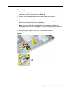
7. Reconnect the ATA controller board to the drive interconnect and logic boards.
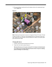
Note:
When replacing the ATA controller board, align it over the two pairs of
connectors on the drive interconnect and logic boards, making sure the “MLB” arrow
printed on it points toward the logic board, and press down.
(Figure 12)
Figure 12