


v AIMB-256 User Manual
Contents
Chapter 1 Production Introduction......................1
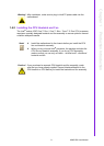
1.1 Before you Proceed .................................................................................. 2
1.2 Motherboard Overview.............................................................................. 2
1.2.1 Placement Direction...................................................................... 2
1.2.2 Screw Holes.................................................................................. 3
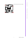
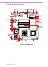
1.3 Motherboard Layout .................................................................................. 4
Figure 1.1 Motherboard Layout ................................................... 4
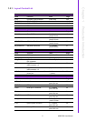
1.3.1 Layout Content List ....................................................................... 5
Table 1.1: Slots............................................................................ 5
Table 1.2: Jumpers...................................................................... 5
Table 1.3: Rear Panel Connector ................................................ 5
Table 1.4: Internal Connector ...................................................... 5
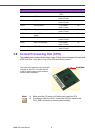
1.4 Central Processing Unit (CPU) ................................................................. 6
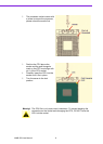
1.4.1 Installing the CPU ......................................................................... 7
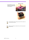
1.4.2 Installing the CPU Heatsink and Fan ............................................ 9
1.4.3 Uninstalling the CPU Heatsink and Fan...................................... 12
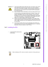
1.5 System Memory ...................................................................................... 13
1.5.1 DIMM Sockets Location .............................................................. 13
1.5.2 Memory Configurations............................................................... 14
1.5.3 Installing a DDR2 DIMM ............................................................. 14
1.5.4 Removing a DDR2 DIMM ........................................................... 16
1.6 Expansion Slots ...................................................................................... 16
1.6.1 Installing an Expansion Card ...................................................... 16
1.6.2 Configuring an Expansion Card .................................................. 17
1.6.3 Standard Interrupt Assignments ................................................. 17
Table 1.5: Standard Interrupt Assignments ............................... 17
1.6.4 PCI Slots ..................................................................................... 17
1.7 Jumpers .................................................................................................. 18
1.7.1 Clear CMOS (CCMOS1)............................................................. 18
1.7.2 COM1 RI/+5 V/+12 V Selection (JCOMPWR1, JCOMPWR2).... 19
1.7.3 COM2 RI/+5 V/+12 V Selection (JCOMPWR1, JCOMPWR2).... 19
1.7.4 COM3 RI/+5 V/+12 V Selection (JCOMPWR3, JCOMPWR4).... 20
1.7.5 COM4 RI/+5 V/+12 V Selection (JCOMPWR3, JCOMPWR4).... 20
1.7.6 SM Power Connector (SM_PWRBTN1) ..................................... 21
1.8 Connectors.............................................................................................. 21
1.8.1 Rear Panel Connectors............................................................... 21
Table 1.6: Rear Panel Connectors ............................................ 21
Table 1.7: LEDs......................................................................... 22
Table 1.8: Rear Panel Connectors ............................................ 22
1.8.2 Amplifier Connector (AMPJ1) (Optional)..................................... 23
1.8.3 ATX Power Connector (ATXPWR1) ........................................... 23
1.8.4 Serial Port 3 Connector (COM3)................................................. 24
1.8.5 Serial Port 4 Connector (COM4)................................................. 24
1.8.6 CPU Fan Connector (CPU_FAN1) ............................................. 25
1.8.7 Power Fan Connector (PWR_FAN1) .......................................... 25
1.8.8 System Panel Connector (FPIO1) .............................................. 26
1.8.9 Primary IDE Connector (IDE1).................................................... 27
1.8.10 LVDS Connector (JLVDS1) ........................................................ 27
1.8.11 LCD Inverter Connector (JBKL1) ................................................ 28
1.8.12 Digital I/O Connector (JDIO1) ..................................................... 28
1.8.13 SPI Connector (JSPI1)................................................................ 29
1.8.14 Digital Audio Connector (SPDIF_OUT2)..................................... 29
1.8.15 Serial SATA Connector [Black] (SATA1, SATA2, SATA3) ......... 30
1.8.16 USB 2.0 Connector (USB3, USB4, USB5) ................................. 30