


Chapter 3 45
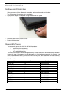
External Module Disassembly Process
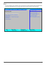
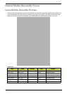
External Modules Disassembly Flowchart
The flowchart below gives you a graphic representation on the entire disassembly sequence and instructs you
on the components that need to be removed during servicing. For example, if you want to remove the main
board, you must first remove the keyboard, then disassemble the inside assembly frame in that order.
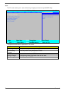
Screw List
Step Screw Quantity Color Part No.
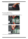
Memory Cover M2.5*8 (NL) 4 Black MA000005YG0
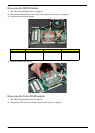
HDD Cover M2*6 (NL) 2 Black MMCK20060G0
WLAN Cover M2.5*8 (NL) 4 Black MA000005YG0
WLAN Module M2*3 (NL) 2 Black MA0000060G0
HDD Carrier M3*3 (NL) 4 Silver MAAA03032G0
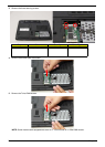
ODD Module M2.5*5(NL) 1 Black MA000002NG0
ODD Bracket M2*3 (NL) 3 Black MA0000060G0