


68 Aspire AX1400 Service Guide
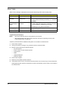
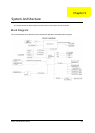
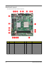
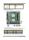
Mainboard Layout
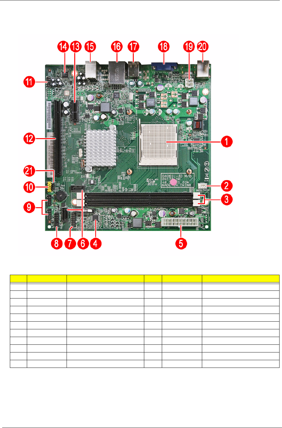
This section shows the major mainboard components.
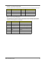
No. Label Description No. Label Description
1 U1 CPU socket 12 PCIEX16 PCIEX16 Slot
2 CPUFAN1 CPU cooling fan connector 13 PCIEX1 PCIEX1 36-pin slot
3 DIMM1-2 DDR3 240-pin slots 14 U2 ALC662
4 U23 ITE 8758 15 AUDJACK2 Line in/Line Out/MIC
5 PWR2 Standard 24-pin power connector 16 USBLAN1 RJ45+USB connector
6 SATA1-2 Serial ATA connectors 17 USBR1 USB-A 8P connector
7 DEBUGH1 12-pin DEBUG port 18 VGA1 VGA connector
8 LEDH1 12-pin power cable header 19 PWR1 ATX 4-pin connector
9 USBF 2-3 Front panel USB header 20 KBMSCONN1 Keyboard and mouse connectors
10 USBF 1 Front panel card reader header 21 JBIOS1 Clear CMOS jumper
11 AUDIOF1 Front panel audio jack header