


Aspire AX1400 Service Guide 75
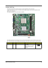
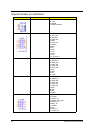
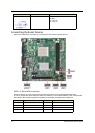
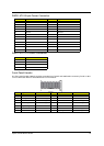
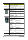
PWR2: ATX 24-pin Power Connector
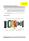
PWR1: ATX 12V Power Connector
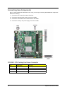
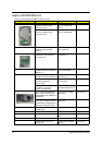
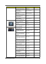
Front Panel Header
The front panel header (LEDH1) provides a standard set of switch and LED headers commonly found on ATX
or micro-ATX cases. Refer to the table below for
information:
Pin Signal Name Pin Signal Name
1 +3.3V 13 +3.3V
2 +3.3V 14 -12V
3 Ground 15 Ground
4 +5V 16 PS_ON
5 Ground 17 Ground
6 +5V 18 Ground
7 Ground 19 Ground
8 PWRGD 20 -5V
9 +5VSB 21 +5V
10 +12V 22 +5V
11 +12V 23 +5V
12 +3.3V 24 Ground
Pin Signal Name
1 Ground
2 Ground
3 +12V
4 +12V
Pin Signal Name Function Pin Signal Name Function
1 VCC Reset Switch (+) 2 GLED0 *MSG LED (+)
3 HDD_LEDN Hard disk LED (-) 4 GLED1 *MSG LED (-)
5 GND Reset Switch (-) 6 PWRSW Power Switch (+)
7 HWRST_L Reset Switch (+) 8 GND Power Switch (-)
9 F_PANEL_DET Reserved 10 KEY No pin
11 NC Reserved 12 VCC Reset Switch (+)
13 NC Reserved 14 F_LAN_LED Reset Switch (+)
LEDH1