


30 ASUS MEB-VM User’s Manual
III. HARDWARE SETUP
Connectors
III. H/W SETUP
For Items 19-26
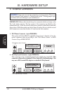
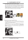
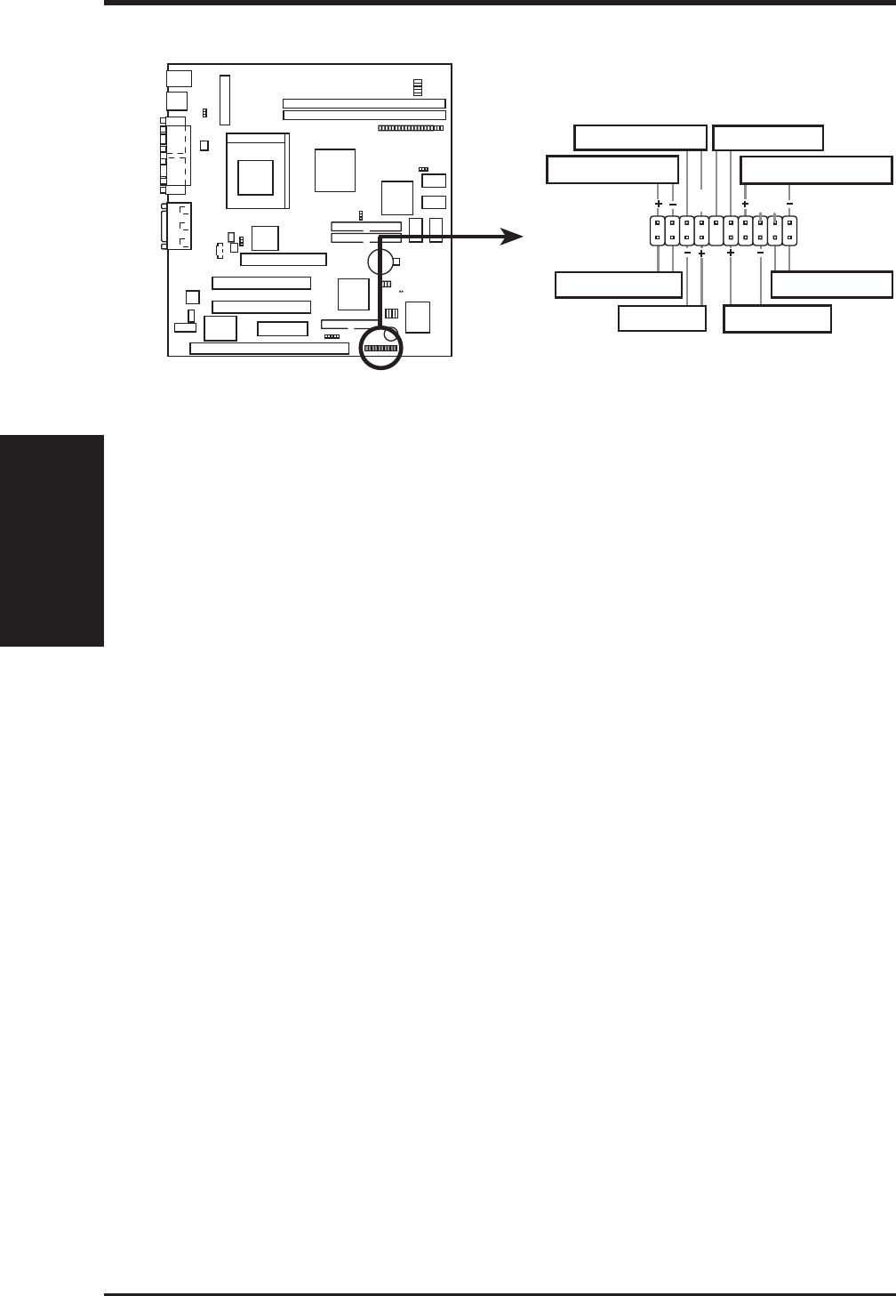
MEB-VM System Panel Connectors
GND
Keyboard Lock
GND
GND
Message LED
SMI Switch
Reset Switch
Power LED
IDE LED
Power Switch
System Speaker
01
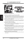
19. ATX Power Switch/Soft Power Switch Lead (2-pin PWR)
The system power can be controlled by a momentary switch connected to this
lead. Pushing the button once will switch the system between ON and OFF.
Pushing the switch while in the ON mode for more than 4 seconds will turn the
system off. The system power LED shows the status of the system’s power.
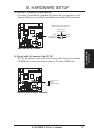
20. IDE Activity LED (2-pin IDELED)
This 2-pin connector supplies power to the cabinet’s IDE activity LED. Read
and write activity by devices connected to the Primary or Secondary IDE con-
nectors will cause the LED to light up.
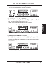
21. System Power LED Lead (3-1 pin PLED)
This 3-1 pin connector connects the system power LED, which lights when the
system is powered on and blinks when it is in sleep mode.
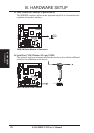
22. Reset Switch Lead (2-pin RESET)
This 2-pin connector connects to the case-mounted reset switch for rebooting
your computer without having to turn off your power switch This is a preferred
method of rebooting in order to prolong the life of the system’s power supply.
23. Message LED Lead (2-pin MLED)
This indicates whether a message has been received from a fax/modem. The
LED will remain lit when there is no signal and blink when there is data transfer
or messages waiting in the inbox. This function requires ACPI OS support.
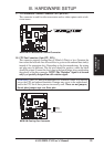
24. Keyboard Lock Switch Lead (2-pin KEYLOCK)
This 2-pin connector connects to the case-mounted key switch to allow key-
board locking.