


34 ASUS A7M266-D User’s Manual
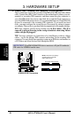
Connectors
3. H/W SETUP
3. HARDWARE SETUP
®
A7M266-D
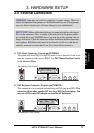
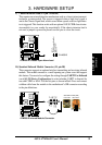
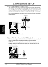
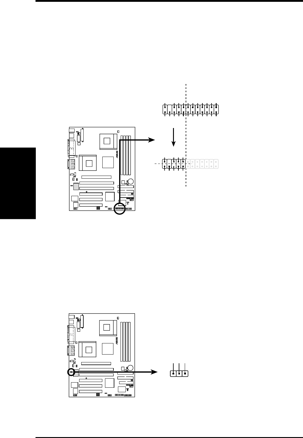
A7M266-D Front Panel Connector
+5VSB
NC
CHASSIS#
+5 V
PCIRST#
GND
CIRRX
EXTSMI#
MLED-
NC
BATT
NC
SMBDATA
GND
+3VSB
IRRX
IRTX
LOCKKEY
NC
NC
+5V SMBCLK
AFPANEL
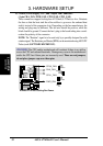
+5VSB
NC
+5 V
GND
CIRRX
NC
GND
IRRX
IRTX
CIR
SIR
IR_CON
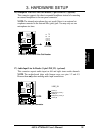
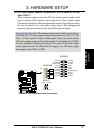
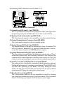
14) ASUS iPanel Connector (24-1 pin AFPANEL)
This connector allows you to connect an optional ASUS iPanel, an easy to ac-
cess drive bay with front I/O ports, status LEDs, and space reserved for a hard
disk drive. If you are not using an ASUS iPanel, you can connect an optional
wireless transmitting and receiving infrared module to the SIR connector or an
optional consumer infrared connector set to the CIR and SIR connectors for
both wireless transmitting and remote control functions through one external
infrared module.
®
A7M266-D
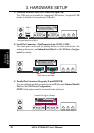
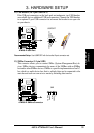
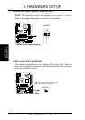
A7M266-D Internal Microphone Connector
MIC Power
13
MIC Input
Ground
MIC2
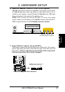
15) Internal Microphone Connector (3-pin MIC2) (optional)
This connector supports the chassis-mounted microphone to the motherboard
instead of connecting an external microphone to the ATX connector.
NOTE: The internal microphone does not work if there is an external mi-
crophone connected to the external Mic (pink) jack. You may only use one
microphone at a time.