


ASUS A7N266-VM motherboard user guide
9
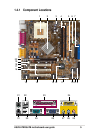
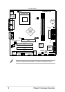
2.2 Layout contents
CPU, Memory and Expansion Slots
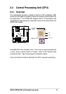
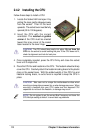
1) Socket 462 p. 12 CPU Support
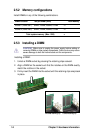
2) DIMM 1/2 p. 14 System Memory Support
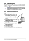
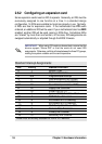
3) PCI 1/2/3 p. 18 32-bit PCI Bus Expansion Slots
4) AGP 4x p. 18 Accelerated Graphics Slot
Motherboard Settings (Switches and Jumpers)
1) BSEL0, BSEL1 p. 19 CPU:DRAM Frequency Setting (Various)
2) KBPWR p. 20 Keyboard Wake Up (+5V / +5VSB)
3)
USBPWR_01,_23,_45
p. 21 USB Device Wake-up (Disable/Enable)
4) CLRTC p. 22 Clear RTC RAM (CLRTC)
Connectors
1) PS2KBMS p. 23 PS/2 Mouse Port (6 pin female)
2) PS2KBMS p. 23 PS/2 Keyboard Port (6 pin female)
3) USB p. 24 Universal Serial Bus Ports 0, 1
(Two x 4 pin female)
4) COM1 / COM2 p. 24 Serial Ports (One 9-pin, One 10-1 pin)
5) VGA p. 25 Monitor Output Connector (Blue 15-pin)
6) PRINTER p. 25 Parallel Port (25 pin female)
7) GAME_AUDIO p. 25 Game/MIDI Ports (Gold 15-pin) (Optional)
8) AUDIO p. 26 Audio Connectors (Three 1/8” AUDIO) (Optional)
9) IDELED p. 26 IDE Activity LED (Two 40-1 pin)
10) FLOPPY p. 27 Floppy Disk Drive Connector (34-1 pin)
11) PRIMARY / SEC. IDE p. 27 IDE Connectors (Two 40-1 pin)
12) CPU_FAN p. 28
CPU Fan Connector (3 pin)
13) AAPANEL p. 28 ASUS Front Panel Audio Connector (10 pin)
14) ATXPWR p. 29 ATX Power Supply Connector (20 pin)
15) SMB p. 29 SMBus Connector (6-1 pin)
16)
CD_IN1, AUX
p. 30 Internal Audio Connectors (Two 4 pin)
(Optional)
17) SPDIF1 p. 30 Digital Audio Interfaces (4-1 pin SPDIF1)
(Optional)
18) USB_23, _45 p. 31 USB Headers (Two 10-1 pin)
18) IR p. 31 Infrared module connector (Two 5-1 pin)
20) PWR_LED (Panel) p. 32
System Power LED Lead (3-1 pin)
21) KEYLOCK (Panel) p. 32 Keyboard Lock Switch Lead (2 pin)
22) SPEAKER (Panel) p. 32 System Warning Speaker Lead (4 pin )
23) LED (Panel) p. 32 System Message LED Lead (2 pin)
24) SMI (Panel) p. 32 System Management Interrupt Lead (2 pin)
25) PWR (Panel) p. 32 ATX Power Switch / Soft-Off Switch Lead (2 pin)
26) RESET (Panel) p. 32 Reset Switch Lead (2 pin)