


ASUS A7V User’s Manual 39
3. HARDWARE SETUP
Connectors
3. H/W SETUP
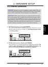
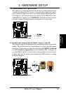
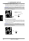
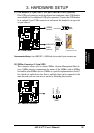
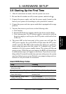
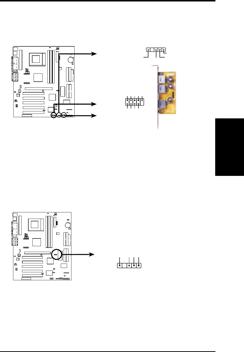
17) USB Headers (5-1 pin USB3A, 10-1 pin USBPORT/USB3) (optional)
If the USB port connectors on the back panel are inadequate, three USB headers
are available for five additional USB port connectors. Connect the USB headers
to an optional 3-port USB connector set and mount the bracket to an open slot
on your chassis.
A7V USB Ports
USBPORT
USB Power
USBP2–
USBP2+
GND
NC
USB Power
USBP3–
USBP3+
GND
15
610
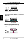
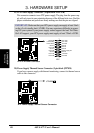
USB3
(Optional)
USB3A
(Optional)
USB Power
GND
USBP+
USBP-
1
01
01
01
A7V
Bundled 3-port
USB Connector Set
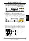
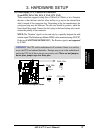
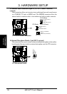
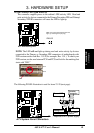
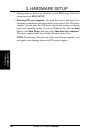
18) SMBus Connector (5-1 pin SMB)
This connector allows you to connect SMBus (System Management Bus) de-
vices. SMBus devices communicate by means of the SMBus with an SMBus
host and/or other SMBus devices. SMBus is a specific implementation of an I
2
C
bus, which is a multi-device bus; that is, multiple chips can be connected to the
same bus and each one can act as a master by initiating data transfer.
SMBCLK
Ground
SMBDATA
+5V
1
A7V SMBus Connector
SMB
0 1
0 1
0 1
A7V
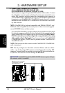
Recommended Setup: Use USBPORT + USB3A with the bundled 3-port connector set.