


ASUS A7V User’s Manual 41
3. HARDWARE SETUP
Connectors
3. H/W SETUP
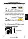
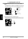
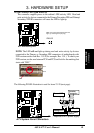
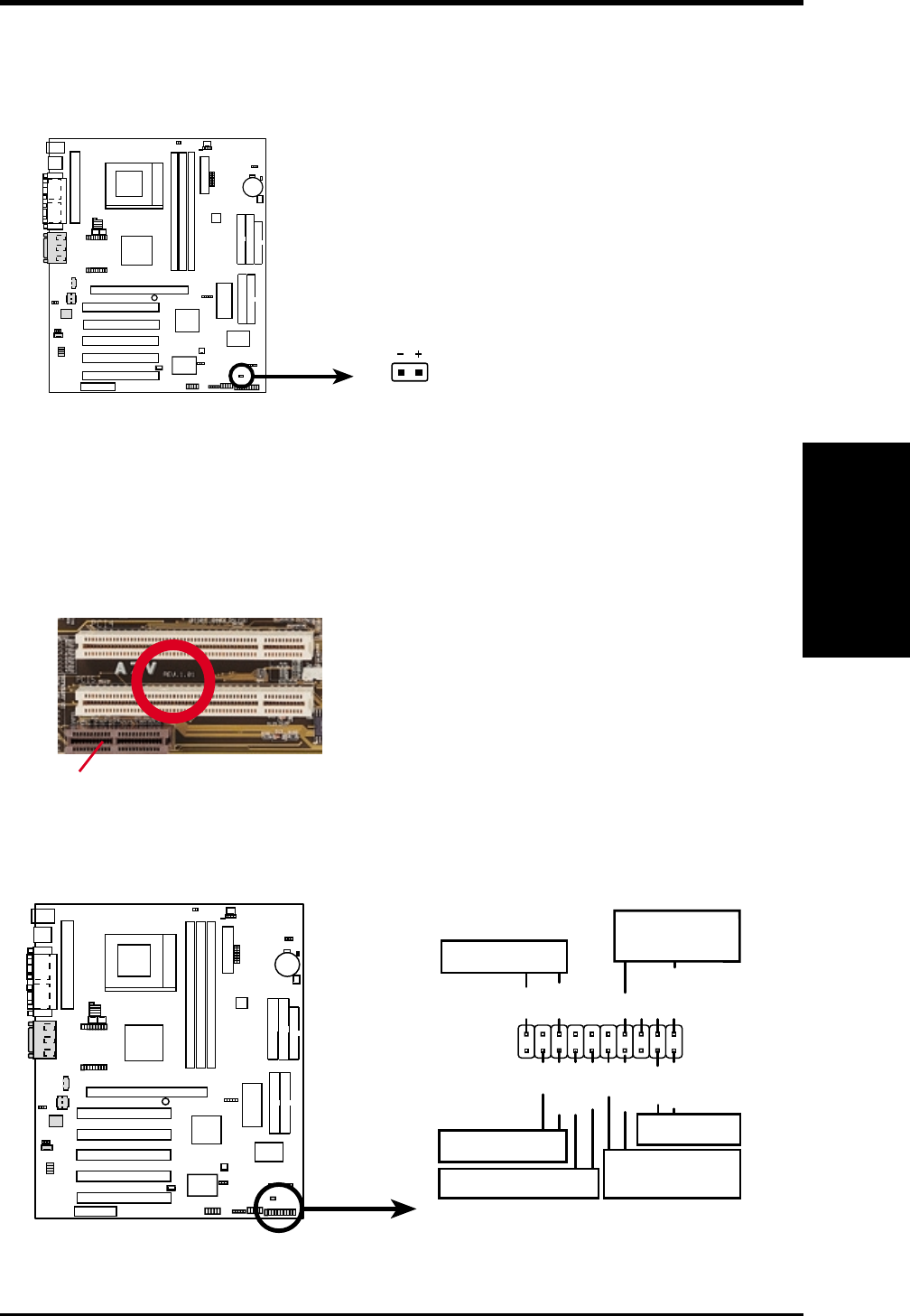
21) IDE Activity LED (2-pin IDELED)
This connector supplies power to the cabinet’s IDE activity LED. Read and
write activity by devices connected to the Primary/Secondary IDE and Primary/
Secondary ATA100 connectors will cause the LED to light up.
A7V IDE Activity LED
TIP: If the case-mounted LED does not
light, try reversing the 2-pin plug.
IDELED
0 1
0 1
0 1
A7V
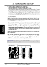
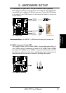
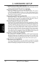
NOTE: The LED will not light up during read and write activity by devices
connected to the Primary or Secondary IDE connectors of motherboards with
PCB versions earlier than Rev. 1.01.P (for example, Rev. 1.01.). To check your
PCB version, see the area between PCI4 and PCI5 and look for the marking that
starts with “REV.”
PCI5
PCI4
AMR
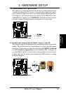
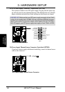
The following PANEL illustration is used for items 23–28 (next page).
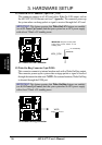
A7V System Panel Connectors
*
Requires an ATX power supply.
PLED
Ground
TB_LED
PWR
+5 V
+5V
Speaker
Speaker
Connector
Power LED
Ground
+5 V
Reset SW
SMI Lead
Message LED
ExtSMI#
Ground
Reset
Ground
Ground
ATX Power
Switch*
01
01
01
A7V