ASUS A7V User’s Manual 59
4. BIOS SETUP
4. BIOS SETUP
Main Menu
Halt On [All Errors]
This field determines which types of errors will cause the system to halt.
Configuration options: [All Errors] [No Error] [All but Keyboard] [All but
Disk] [All but Disk/Keyboard]
Installed Memory [XXX MB]
This display-only field displays the amount of conventional memory detected
by the system during bootup. You do not need to make changes to this field.
Language [English]
This allows selection of the BIOS’ displayed language. Currently only English is available.
Supervisor Password [Disabled] / User Password [Disabled]
These fields allow you to set the passwords. To set the password, highlight the appro-
priate field and press <Enter>. Type in a password and press <Enter>. You can type up
to eight alphanumeric characters. Symbols and other keys are ignored. To confirm the
password, type the password again and press the <Enter>. The password is now set to
[Enabled]. This password allows full access to the BIOS Setup menus. To clear the
password, highlight this field and press <Enter>. The same dialog box as above will
appear. Press <Enter> and the password will be set to [Disabled].
A Note about Passwords
The BIOS Setup program allows you to specify passwords in the Main menu. The pass-
words control access to the BIOS during system startup. The passwords are not case sen-
sitive. In other words, it makes no difference whether you enter a password using upper or
lowercase letters. The BIOS Setup program allows you to specify two separate passwords:
a Supervisor password and a User password. When disabled, anyone may access all BIOS
Setup program functions. When enabled, the Supervisor password is required for entering
the BIOS Setup program and having full access to all configuration fields.
Forgot the Password?
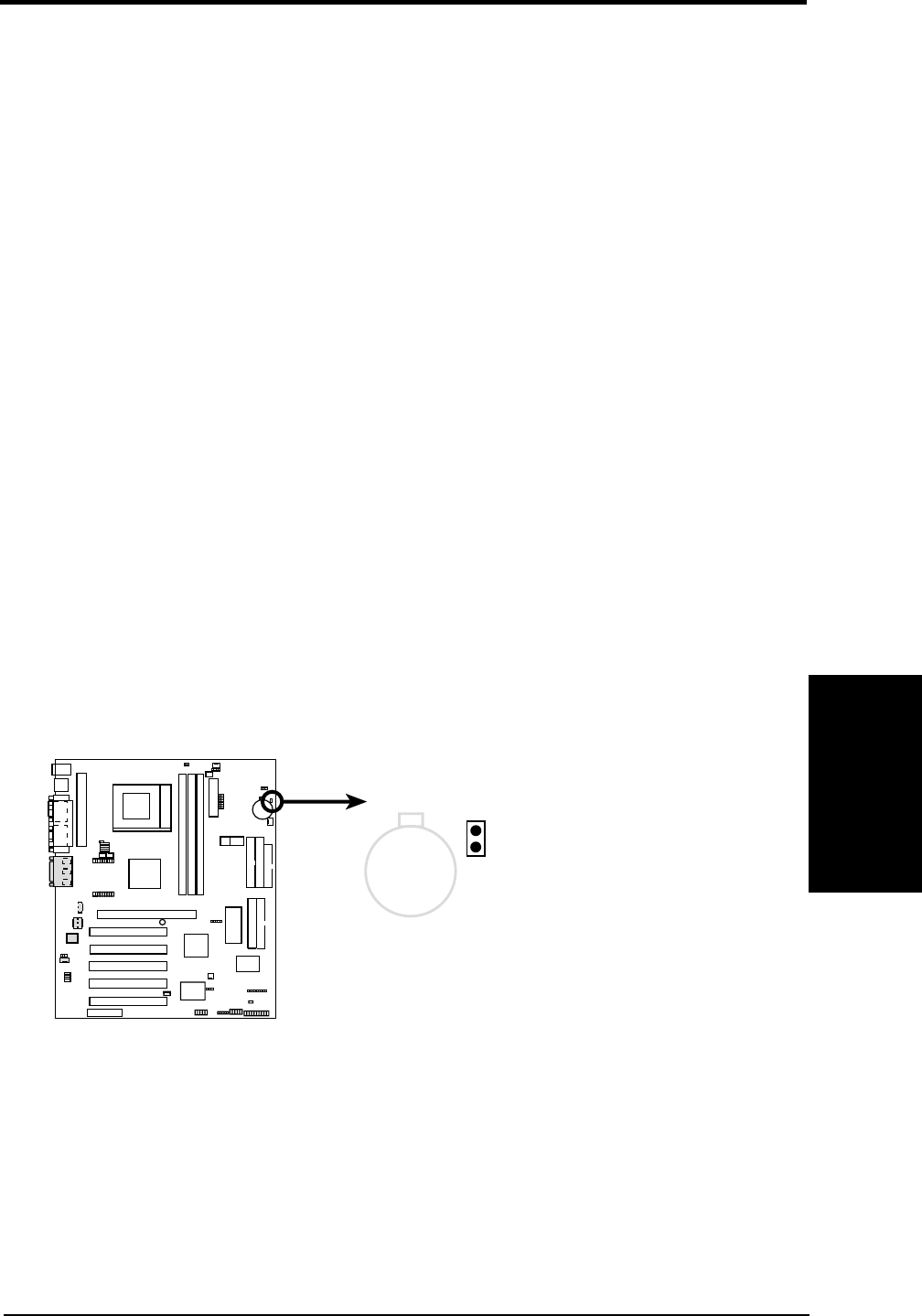
If you forgot the password, you can clear the password by erasing the CMOS Real
Time Clock (RTC) RAM. The RAM data containing the password information is
powered by the onboard button cell battery. To erase the RTC RAM: (1) Unplug
your computer, (2) Short the solder points, (3) Turn ON your computer, (4) Hold
down <Delete> during bootup and enter BIOS setup to re-enter user preferences.
A7V Clear RTC RAM
Short solder points
to Clear CMOS
CLRTC
CR2032 3V
Lithium Cell
CMOS Power
01
01
01
A7V


