


32 ASUS A7VL133-VM User’s Manual
Connectors
3. H/W SETUP
3. HARDWARE SETUP
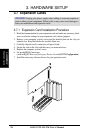
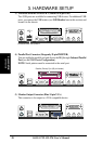
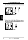
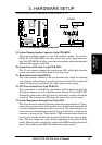
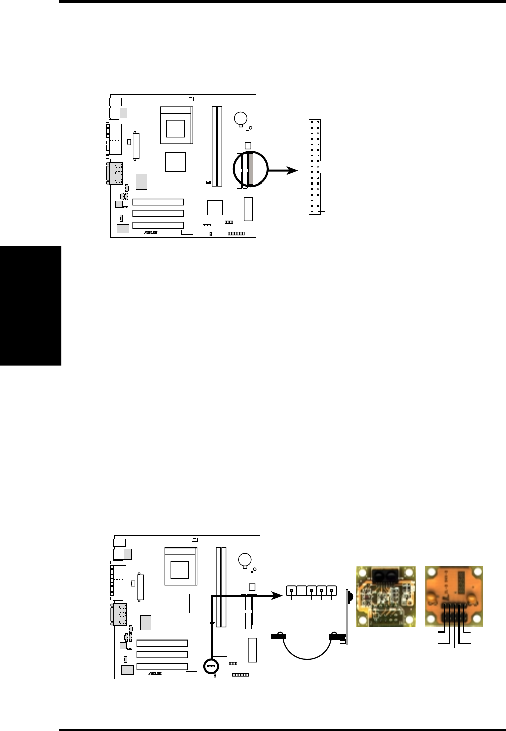
12) Standard and Consumer Infrared Module Connector (5 pin IR)
This connector supports an optional wireless transmitting and receiving infrared
module. This module mounts to a small opening on system cases that support
this feature. You must also configure the setting through UART2 Use Infrared
(see 4.4.2 I/O Device Configuration) to select whether UART2 is directed for
use with COM2 or IrDA. Use the five pins as shown in Back View and connect
a ribbon cable from the module to the motherboard’s SIR connector according
to the pin definitions.
A7VL133-VM
®
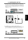
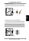
A7VL133-VM Infrared Module Connector
Front View
Back View
+5V
IRTX
IRRX
(NC)
GND
IR
+5V
IRRX
IRTX
GND
1
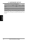
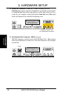
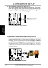
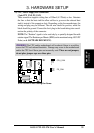
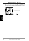
11) Floppy Disk Drive Connector (34-1 pin FLOPPY)
This connector supports the provided floppy drive ribbon cable. After connect-
ing the single end to the board, connect the two plugs on the other end to the
floppy drives. (Pin 5 is removed to prevent inserting in the wrong orienta-
tion when using ribbon cables with pin 5 plugged).
NOTE: Orient the red markings on
the floppy ribbon cable to
PIN 1
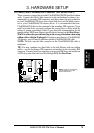
A7VL133-VM Floppy Disk Drive Connector
PIN 1
A7VL133-VM
®