


ASUS A7VL133-VM User’s Manual 35
3. HARDWARE SETUP
Connectors
3. H/W SETUP
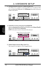
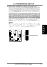
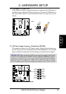
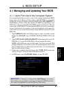
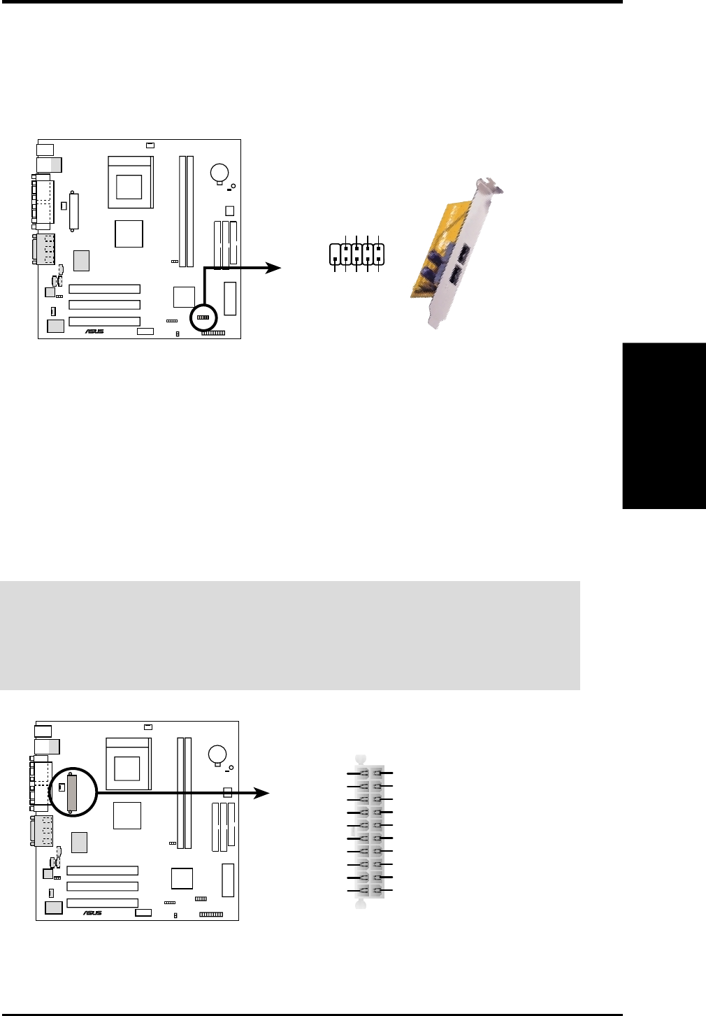
16) USB Header (10-1 pin USB2)
If the USB port connectors on the back panel are inadequate, this USB header is
available for two additional USB port connectors. Connect the USB headers to
the 2-port USB connector set and mount the bracket to an open slot on your
chassis.
A7VL133-VM
®
A7VL133-VM USB Port
USB Power
USBP2–
USBP2+
GND
NC
USB Power
USBP3–
USBP3+
GND
1
5
610
USB2
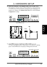
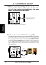
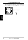
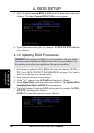
17) ATX Power Supply Connector (20 pin block ATXPWR)
This connector connects to an ATX power supply. The plug from the power sup-
ply will only insert in one orientation because of the different hole sizes. Find the
proper orientation and push down firmly making sure that the pins are aligned.
IMPORTANT: Make sure that your ATX power supply can supply at least 10mA
on the +5-volt standby lead (+5VSB). You may experience difficulty in power-
ing ON your system if your power supply cannot support the load. For Wake-
On-LAN support, your ATX power supply must supply at least 720mA +5VSB.
A7VL133-VM
®
A7VL133-VM ATX Power Connector
+3.3 Volts
-12.0 Volts
Ground
Power Supply On
Ground
Ground
Ground
-5.0 Volts
+5.0 Volts
+5.0 Volts
Power Good
+12.0 Volts
+3.3 Volts
+3.3 Volts
Ground
+5.0 Volts
Ground
+5.0 Volts
Ground
+5V Standby