


ASUS A7V-M User’s Manual 33
3. HARDWARE SETUP
Connectors
3. H/W SETUP
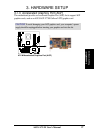
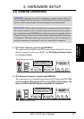
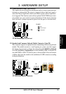
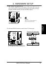
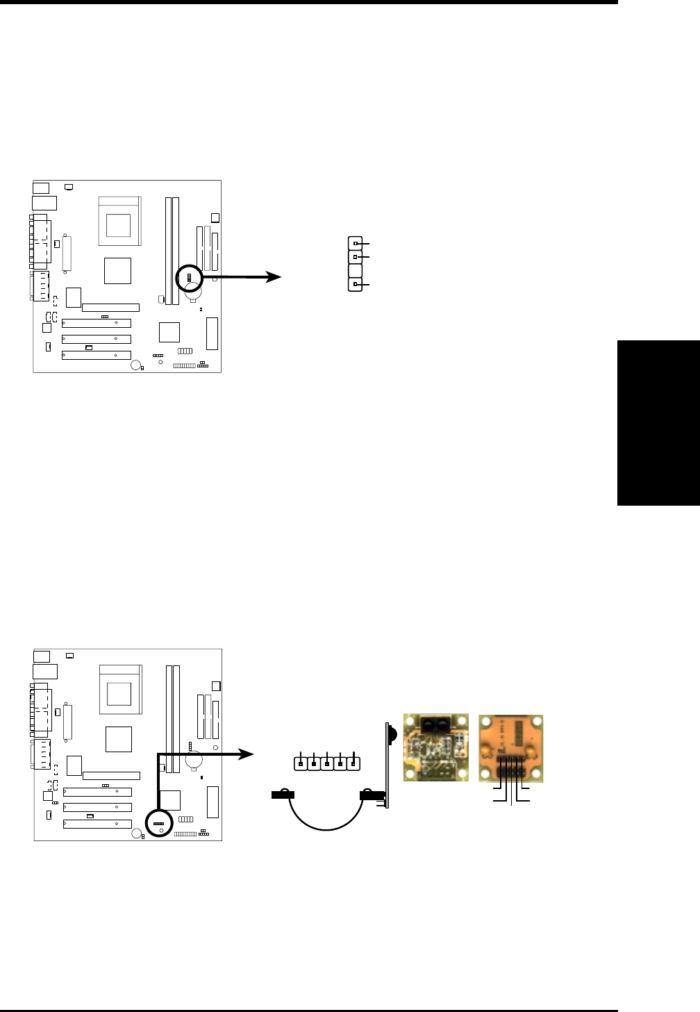
11) Chassis Intrusion Lead (2 pin CHASS)
This requires an external detection mechanism such as a chassis intrusion moni-
tor/sensor or microswitch. The sensor is triggered when a high level signal is
sent to the Chassis Signal lead, which occurs when a panel switch or light detec-
tor is triggered. This function works with an optional ASUS CIDB chassis intru-
sion module (see your vendor for more information). If the chassis intrusion
lead is not used, a jumper cap must be placed over the pins to close the circuit.
+5VSB_MB
Chassis Signal
CHASS
1
GND
A7V-M Chassis Open Alarm Lead
A7V-M
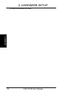
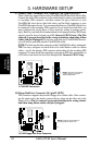
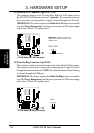
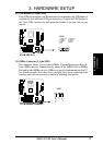
12) Standard and Consumer Infrared Module Connector (5-pin IR)
This connector supports an optional wireless transmitting and receiving infrared
module. This module mounts to a small opening on system cases that support
this feature. You must also configure the setting through UART2 Use Infrared
(see 4.4.2 I/O Device Configuration) to select whether UART2 is directed for
use with COM2 or IrDA. Use the five pins as shown in Back View and connect
a ribbon cable from the module to the motherboard’s SIR connector according
to the pin definitions.
A7V-M Infrared Module Connector
Front View Back View
+5V
IRTX
IRRX
(NC)
GND
+5V
IRRX
IRTX
(NC)
GND
IR
1
A7V-M