


ASUS AT5NM10-I 1-12
8. USB 2.0 ports 3 and 4. These two 4-pin Universal Serial Bus (USB) ports are for
USB 2.0 devices.
9. Video Graphics Adapter (VGA) port. This 15-pin port is for a VGA monitor or other
VGA-compatible devices.
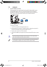
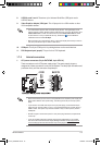
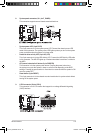
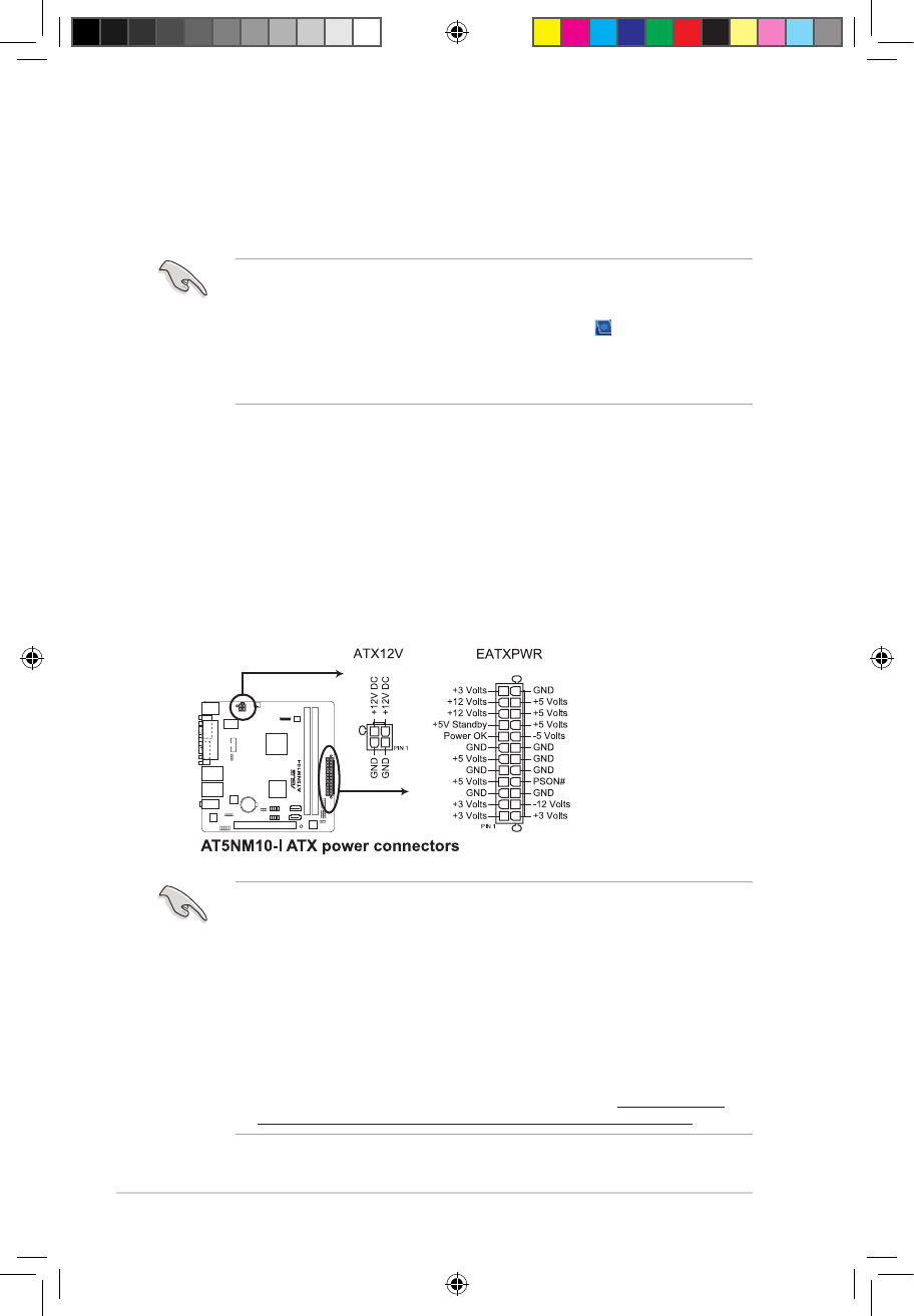
1. ATX power connectors (24-pin EATXPWR, 4-pin ATX12V)
These connectors are for ATX power supply plugs. The power supply plugs are
designed to t these connectors in only one orientation. Find the proper orientation and
push down rmly until the connectors completely t.
• We recommend that you use an ATX 12V Specication 2.0-compliant power supply unit
(PSU) with a 450W or lower power rating. This PSU type has 24-pin and 4-pin power
plugs.
• If you intend to use a PSU with 20-pin and 4-pin power plugs, ensure that the 20-pin
power plug can provide at least 15 A on +12 V and that the PSU has a power rating of
450W or lower. The system may become unstable or may not boot up if the power is
inadequate.
• DO NOT forget to connect the 4-pin ATX +12V power plug. Otherwise, the system will
not boot up.
• If you are uncertain about the minimum power supply requirement for your system,
refer to the Recommended Power Supply Wattage Calculator at http://support.asus.
com/PowerSupplyCalculator/PSCalculator.aspx?SLanguage=en-us for details.
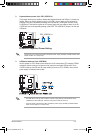
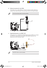
1.7.2 Internal connectors
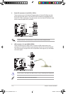
10. COM port. This 9-pin COM1 port is for pointing devices or other serial devices.
11. PS/2 Keyboard port (purple). This port is for a PS/2 keyboard.
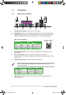
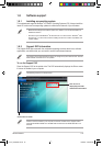
• This motherboard supports VGA and LVDS display devices. In Single Display mode,
use the hot keys to switch between VGA to LVDS device or vice versa. By default, press
<Ctrl>+<Alt>+<F1> to switch to VGA device and press <Ctrl>+<Alt>+<F3> to switch
to LVDS device. To set your preferred hot keys, double-click from the Windows
notication area and select Hot Keys.
• Before removing the current display device, connect the display device that you want to
use, then press the hot keys to switch to that device.
E5179_AT5NM10-I.indb 12 12/22/09 5:55:59 PM