


36 ASUS CUA266 User’s Manual
3. HARDWARE SETUP
Connectors
3. H/W SETUP
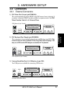
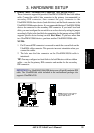
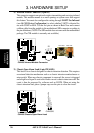
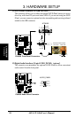
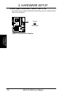
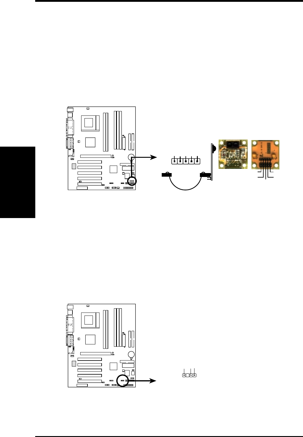
8) Infrared Module Connector (5-pin IR)
This connector supports an optional wireless transmitting and receiving infrared
module. This module mounts to a small opening on system cases that support
this feature. You must also configure the setting through UART2 Use Infrared
(see 4.4.2 I/O Device Configuration) to select whether UART2 is directed for
use with COM2 or IrDA. Use the five pins as shown in Back View and connect
a ribbon cable from the module to the motherboard SIR connector according to
the pin definitions. (NOTE: The SIR module does not come with the motherboard
package. The CIR module is currently not available.)
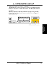
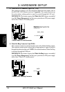
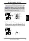
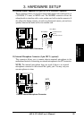
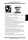
9) Chassis Open Alarm Lead (4-pin CHASSIS)
This lead is for a chassis designed for chassis intrusion detection. This requires
an external detection mechanism such as a chassis intrusion monitor/sensor or
microswitch. When any chassis component is removed, the sensor is triggered
and a high-level signal is sent to this lead to record a chassis intrusion event.The
event is then be processed by software such as LDCM. When not using the
chassis intrusion lead, place a jumper cap over the pins to close the circuit.
CUA266
0101
CUA266 Chassis Open Alarm Lead
CHASSIS
+5Volt
(Power Supply Stand By)
Ground
Chassis Signal
1
CUA266
0101
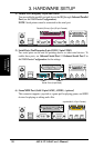
CUA266 Infrared Module Connector
Front View Back View
+5V
IRTX
IRRX
(NC)
GND
+5V
IRRX
IRTX
(NC)
GND
IR
1