


36 ASUS CUW(E)-FX User’s Manual
Connectors
3. H/W SETUP
3. HARDWARE SETUP
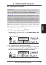
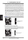
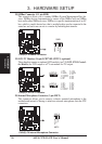
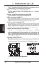
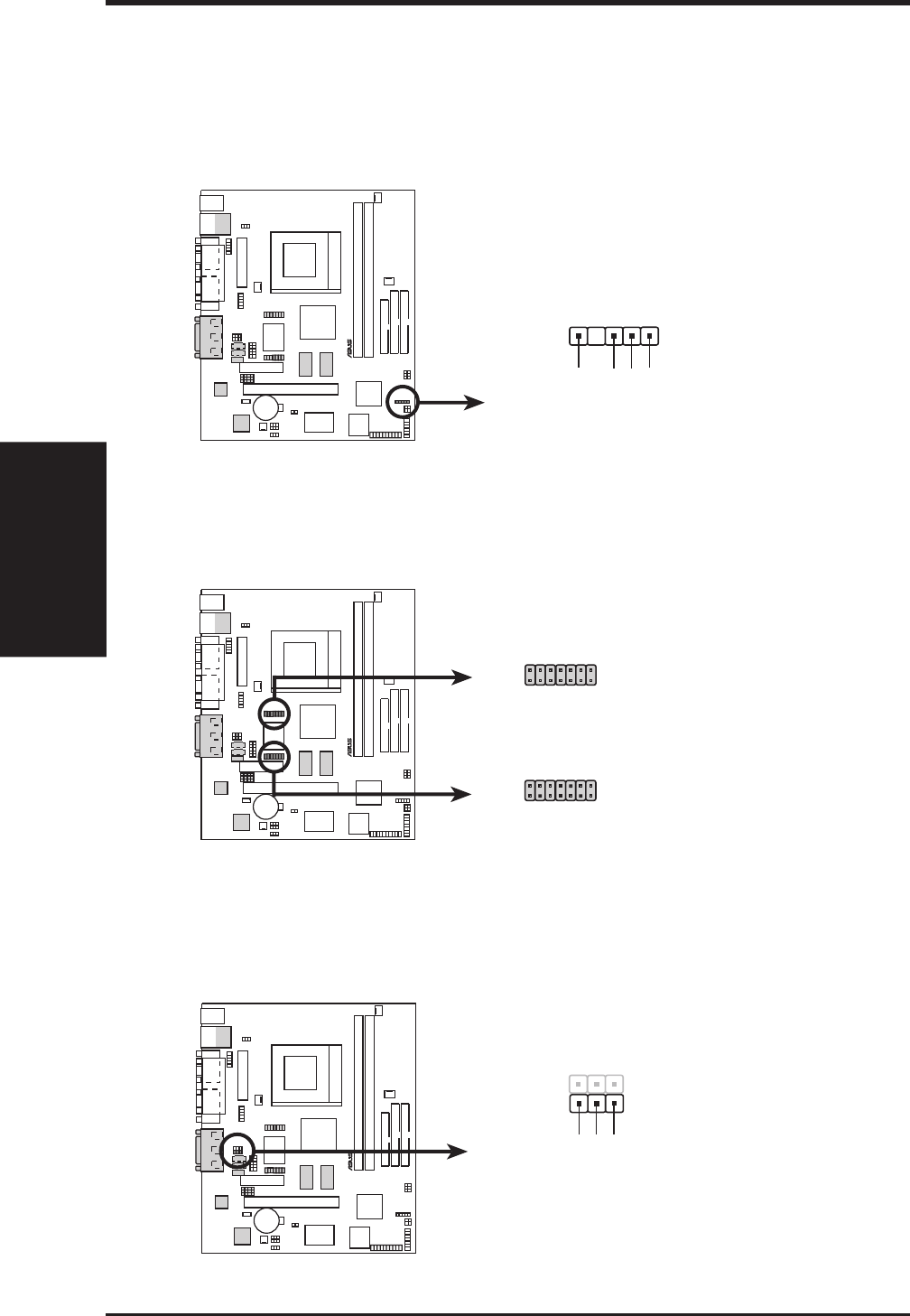
18) SMBus Connector (5-1 pin SMB)
This connector allows you to connect SMBus (System Management Bus) de-
vices. SMBus devices communicate by means of the SMBus with an SMBus
host and/or other SMBus devices. SMBus is a specific implementation of an I
2
C
bus, which is a multi-device bus; that is, multiple chips can be connected to the
same bus and each one can act as a master by initiating data transfer.
SMBCLK
Ground
SMBDATA
+5V
1
CUW(E)-FX SMBus Connector
SMB
®
CUW(E)-FX
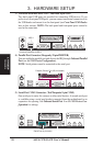
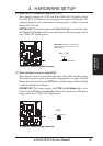
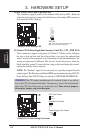
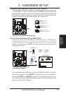
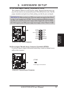
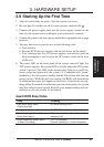
19) LCD-TV Headers (14-pin LCDTV0/LCDTV1) (optional)
These headers require an optional LCD module (see 7.1 ASUS LCD-I Control-
ler Module) for LCD output or a TV-out module for TV output.
®
CUW(E)-FX
CUW(E)-FX LCD-TV Headers
LCDTV0
LCDTV1
1
2
13
14
1
2
13
14
1: GND
3: LTVCL
5: DMSEN
7: TVVSYNC
9: TVHSYNC
11: DD3
13: DD1
2: +1.8V
4: LTVDA
6: BLANK#
8: +3V
10: DD4
12: DD2
14: DD0
1: +5V
3: DD10
5: GND
7: DD10
9: DD6
11: CLKOUT0
13: CLKOUT1
2: +5V
4: DD11
6: GND
8: DD11
10: DD7
12: DD9
14: DD5
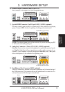
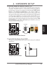
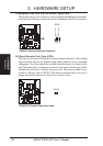
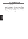
20) Internal Microphone Connector (3 pin MIC2)
This connector allows you to connect a chassis mounted microphone to the
motherboard instead of having to attach an external microphone onto the ATX
connectors.
®
CUW(E)-FX
CUW(E)-FX Internal Microphone Connector
MIC Power
13
MIC Input
Ground
MIC2