


ASUS E45M1-I DELUXE1-14
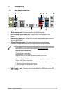
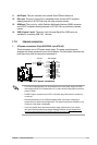
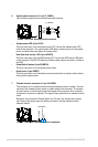
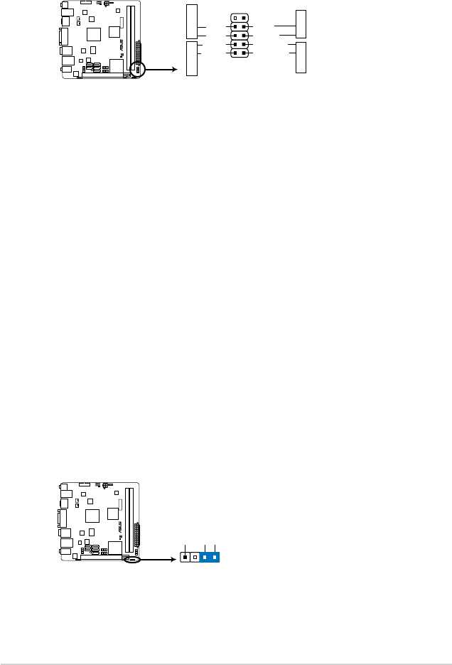
6. System panel connector (10-1 pin F_PANEL)
This connector supports several chassis-mounted functions.
• System power LED (2-pin PLED)
This 2-pin connector is for the system power LED. Connect the chassis power LED
cable to this connector. The system power LED lights up when you turn on the system
power, and blinks when the system is in sleep mode.
• Hard disk drive activity LED (2-pin +HDLED)
This 2-pin connector is for the HDD Activity LED. Connect the HDD Activity LED cable
to this connector. The IDE LED lights up or ashes when data is read from or written to
the HDD.
• Power/Soft-off button (2-pin PWRBTN)
This 2-pin connector is for the system power button.
• Reset button (2-pin RESET)
This 2-pin connector is for the chassis-mounted reset button for system reboot without
turning off the system power.
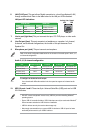
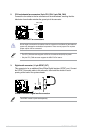
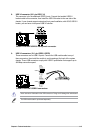
7. Chassis intrusion connector (4-1 pin CHASSIS)
This connector is for a chassis-mounted intrusion detection sensor or switch. Connect
one end of the chassis intrusion sensor or switch cable to this connector. The chassis
intrusion sensor or switch sends a high-level signal to this connector when a chassis
component is removed or replaced. The signal is then generated as a chassis intrusion
event.
By default, the pin labeled “Chassis Signal” and “Ground” are shorted with a jumper
cap. Remove the jumper caps only when you intend to use the chassis intrusion
detection feature.
E35M1-I DELUXE
E45M1-I DELUXE System panel connector
PIN 1
PWRBTN
GND
PWR
PLED-
PLED+
Reset
Ground
IDE_LED-
IDE_LED+
F_PANEL
PLED
+HDLED RESET
E35M1-I DELUXE
E45M1-I DELUXE Chassis intrusion connector
+5VSB_MB
Chassis Signal
GND
CHASSIS