


ASUS F2A85-M
1-27
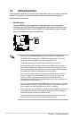
• For a fully congured system, we recommend that you use a power supply unit
(PSU) that complies with ATX 12 V Specication 2.0 (or later version) and provides a
minimum power of 300 W.
•
DO NOT forget to connect the 4-pin ATX +12V power plug. Otherwise, the system will
not boot up.
• We recommend that you use a PSU with higher power output when conguring a
system with more power-consuming devices. The system may become unstable or
may not boot up if the power is inadequate.
•
If you are uncertain about the minimum power supply requirement for your system,
refer to the Recommended Power Supply Wattage Calculator at http://support.asus.
com/PowerSupplyCalculator/PSCalculator.aspx?SLanguage=en-us for details.
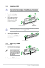
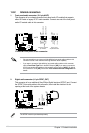
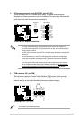
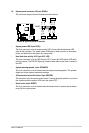
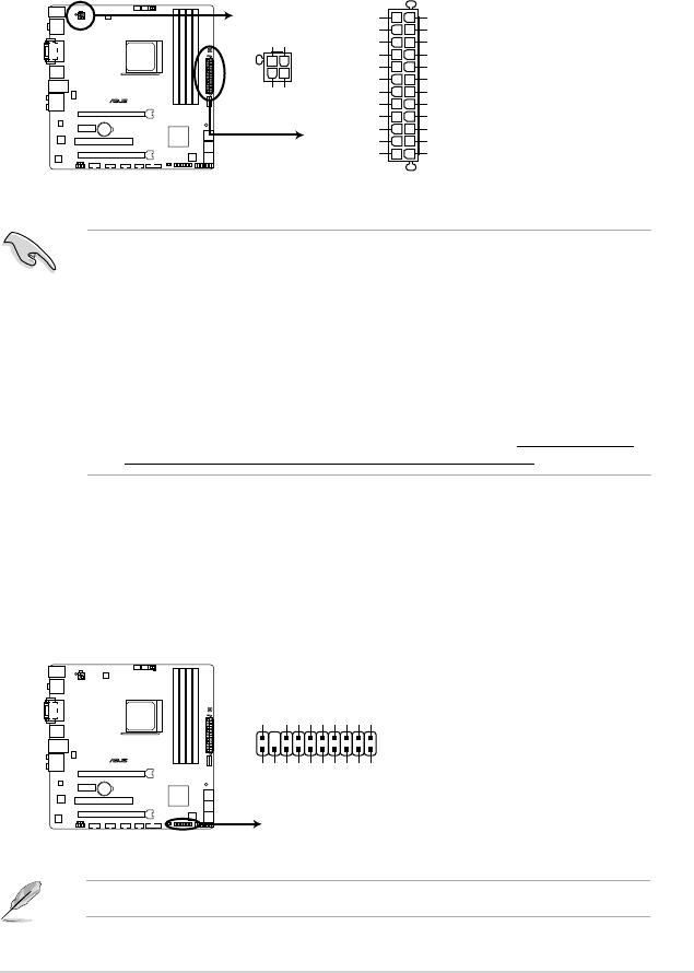
3. ATX power connectors (24-pin EATXPWR, 4-pin ATX12V)
These connectors are for ATX power supply plugs. The power supply plugs are
designed to t these connectors in only one orientation. Find the proper orientation and
push down rmly until the connectors completely t.
F2A85-M
F2A85-M ATX power connectors
EATXPWR
PIN 1
GND
+5 Volts
+5 Volts
+5 Volts
-5 Volts
GND
GND
GND
PSON#
GND
-12 Volts
+3 Volts
+3 Volts
+12 Volts
+12 Volts
+5V Standby
Power OK
GND
+5 Volts
GND
+5 Volts
GND
+3 Volts
+3 Volts
ATX12V
+12V DC
+12V DC
GND
GND
PIN 1
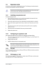
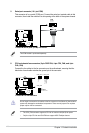
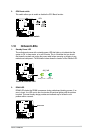
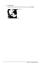
4. TPM connector (20-1 pin TPM)
This connector supports a Trusted Platform Module (TPM) system, which securely
store keys, digital certicates, passwords and data. A TPM system also helps enhance
network security, protect digital identities, and ensures platform integrity.
TPM module is purchased separately.
F2A85-M
F2A85-M TPM Connector
PIN 1
TPM
PCICLK
FRAME
PCIRST#
LAD3
+3V
LAD0
SMBSCL
+3VSB
GND
SB_SUS_STAT
GND
PWROWN
LAD2
LAD1
GND
SMBSDA
SERIRQ
GPIO
RESET