


16 ASUS P2-99 User’s Manual
III. HARDWARE SETUP
Jumpers
III. H/W SETUP
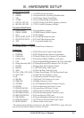
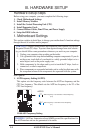
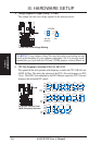
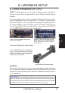
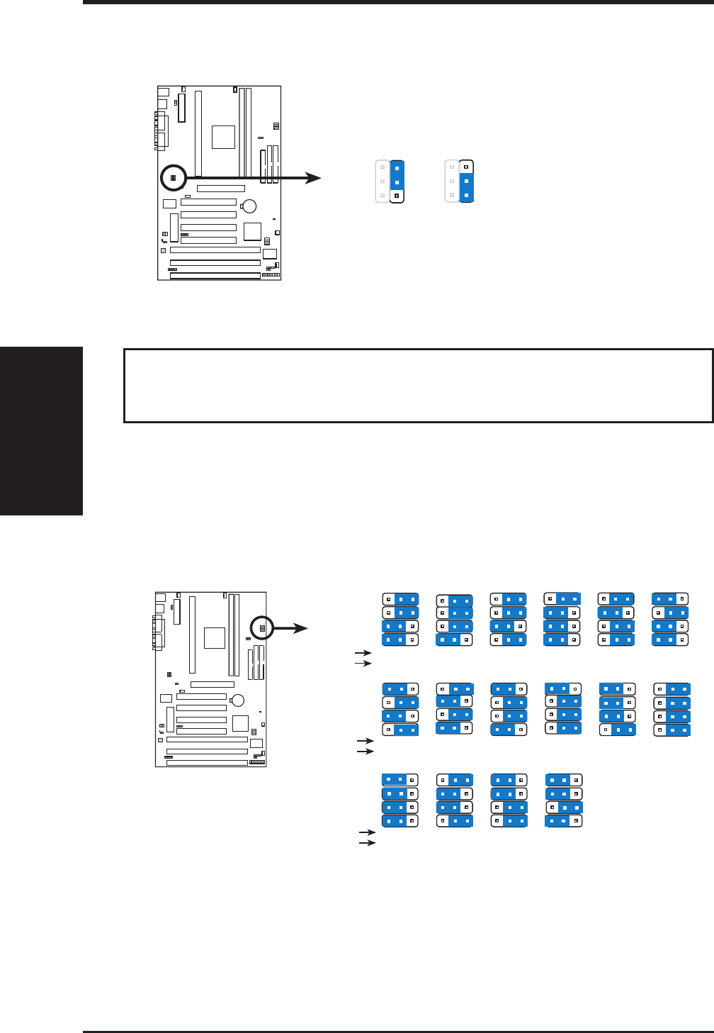
5. CPU Bus Frequency Selection (FS0, FS1, FS2, FS3)
This option tells the clock generator what frequency to send to the CPU, DRAM, and
440ZX AGPset. This allows the selection of the CPU’s External frequency (or BUS
Clock). The BUS Clock multiplied by the BUS Multiple equals the CPU’s Internal
frequency (the advertised CPU speed).
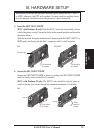
P2-99 CPU External Clock
(BUS) Frequency Selection
105MHz
35MHz
123
103.0MHz
34.3MHz
123
100.30MHz
33.43MHz
123
83.30MHz
41.65MHz
123
75.0MHz
37.5MHz
123
FS1
FS2
FS0
FS3
66.8MHz
33.4MHz
123
CPU
PCI
CPU
PCI
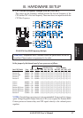
110.00MHz
36.67MHz
112.00MHz
37.33MHz
115.00MHz
38.33MHz
120MHz
40MHz
124MHz
31MHz
124.00MHz
41.33MHz
123 123 123 123 123123
FS1
FS2
FS0
FS3
133.0MHz
33.3MHz
133.00MHz
44.33MHz
140MHz
35MHz
150.0MHz
37.5MHz
123 123 123 123
FS1
FS2
FS0
FS3
CPU
PCI
P2-99
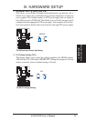
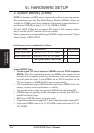
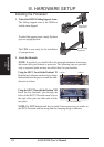
4. Voltage Regulator Output Setting (VCORE)
This jumper sets the core voltage supplied to the microprocessor.
P2-99 CPU Core Voltage Setting
Normal
(Default)
1
VCORE
2
3
Test
1
2
3
P2-99
WARNING! Using a higher voltage Test may help when overclocking but may
result in the shortening of your computer component’s life. It is strongly recom-
mended that you leave both the VIO and VCORE jumpers on their default set-
tings.