


ASUS P2-99B User’s Manual 29
III. HARDWARE SETUP
Connectors
III. H/W SETUP
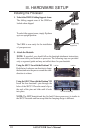
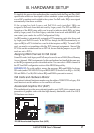
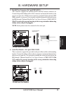
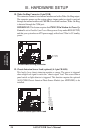
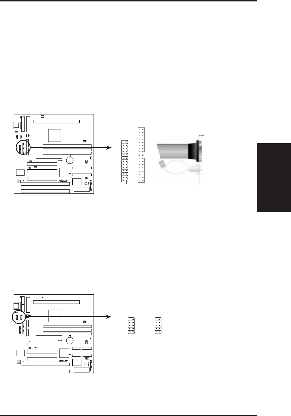
3. Parallel Port Connector (26-1 pin PARALLEL)
This connector supports the included parallel and PS/2 mouse connector set.
Connect the parallel ribbon cable to this connector and mount the bracket to the
case on an open slot. A PS/2 mouse connector is included if the optional USB/
MIR connector is not used. You can make available the parallel port and choose
the IRQ through “Onboard Parallel Port” in Chipset Features of BIOS SETUP.
(Pin 26 is removed to prevent inserting in the wrong orientation when using
ribbon cables with pin 26 plugged).
NOTE: Serial printers must be connected to the serial port.
P2-99B Parallel Connector
Connect the Red
stripe to Pin 1
Pin 1
Parallel Connector
PS/2 Mouse Connector
R
P2-99B
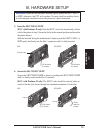
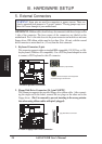
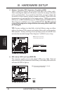
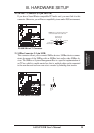
4. Serial Port Headers (10-1 pin COM1/COM2)
These connectors support the provided serial port ribbon cables with mounting
bracket. Connect the ribbon cables to these connectors and mount the bracket to
the case on an open slot. You can make available the serial port and choose the
IRQ through “Onboard Serial Port” in Chipset Features of BIOS SETUP. (Pin
10 is removed to prevent inserting in the wrong orientation when using
ribbon cables with pin 10 plugged).
P2-99B Serial Port Headers
COM 2COM 1
R
P2-99B
Pin 1Pin 1