


30 ASUS P2L97 User’s Manual
III. INSTALLATION
(Connectors)
III. INSTALLATION
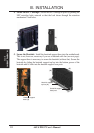
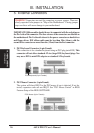
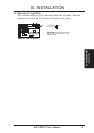
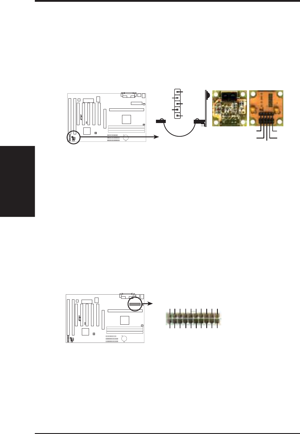
10. IrDA / Fast IR-Compliant infrared module connector (5-pin IR)
This connector supports the optional wireless transmitting and receiving infrared
module. This module mounts to a small opening on system cases that support this
feature. You must also configure the setting through “UART2 Use Infrared” in
Chipset Features Setup to select whether UART2 is directed for use with COM2
or IrDA. Use the five pins as shown on the Back View and connect a ribbon cable
from the module to the motherboard according to the pin definitions.
Front View
+5V
IRTX
IRRX
FIRRX
GND
Back View
Infrared Module Connector
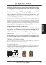
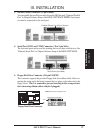
For the infrared feature to be available,
you must connect the optional Infrared
(IrDA) module to the motherboard
+5V
IRRX
IRTX
FIRRX
GND
R
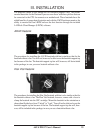
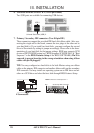
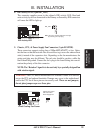
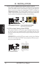
11. ATX Power Supply Connector (20-pin ATXPWR)
This connector connects to a ATX power supply. The plug from the power sup-
ply will only insert in one orientation because of the different hole sizes. Find
the proper orientation and push down firmly but gently making sure that the pins
are aligned.
IMPORTANT: Be sure that the ATX power supply can take at least 10mAmp
load on the 5volt standby lead (5VSB). You may experience difficulty in power-
ing on your system without this.
ATX Power Connector
+3.3Volts
-12.0Volts
Ground
Power Supply On
Ground
Ground
Ground
-5.0 Volts
+5.0 Volts
+5.0 Volts
Power Good
+12.0Volts
+3.3 Volts
+3.3 Volts
Ground
+5.0 Volts
Ground
+5.0 Volts
Ground
+5V Standby
R