


ASUS P4B533 motherboard user guide
1-9
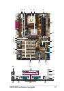
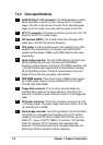
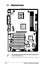
IDE connectors. These dual-channel bus master IDE connectors
support up to four Ultra DMA/100/66, PIO Modes 3 & 4 IDE
devices. Both the primary (blue) and secondary (black) connectors
are slotted to prevent incorrect insertion of the IDE ribbon cable.
DIP switches (DSW2). This 4-switch Dual Inline Package (DIP)
allows you to select the CPU frequency multiple.
Flash EEPROM. This 4Mb firmware contains the programmable
BIOS program.
ASUS ASIC. This chip performs multiple system functions that
include hardware and system voltage monitoring, IRQ routing,
among others.
Standby power LED. This LED lights up if there is a standby
power on the motherboard. This LED acts as a reminder to turn off
the system power before plugging or unplugging devices.
Audio controller. This C-Media 6-channel PCI audio chip supports
legacy audio and HRTF 3D positional audio functions. The chip
also supports 24-bit S/PDIF In (0.5~5V) and S/PDIF Out (44.1K
and 48K formats) professional digital audio interface, and one
MPU-401 UART mode compatible MIDI/game port.
(on audio models only)
PCI slots. These six 32-bit PCI 2.2 expansion slots support bus
master PCI cards like SCSI or LAN cards with 133MB/s maximum
throughput.
Super I/O controller. This Low Pin Count (LPC) interface provides
the commonly used Super I/O functionality. The chipset supports a
high-performance floppy disk controller for a 360K/720K/1.44M/
2.88M floppy disk drive, a multi-mode parallel port, two standard
compatible UARTs, a Standard Infrared (SIR), and a Flash ROM
interface.
AGP warning LED. Serving as a smart burn-out protection for the
motherboard, this red LED lights up if you plug in any 3.3V AGP
card into the AGP slot. When this LED is lit, there is no way you
can turn on the system power even if you press the power button.
AGP slot. This Accelerated Graphics Port (AGP) slot supports 1.5V
AGP4X mode graphics cards for 3D graphical applications.
11
12
13
14
15
16
17
18
19
10