


2-30
Chapter 2: Hardware information
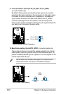
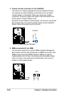
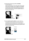
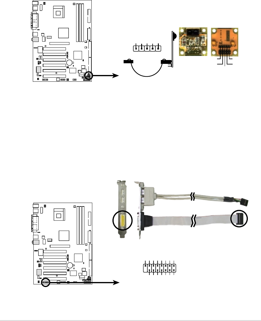
11. Infrared module connector (5-pin IR)
This connector supports an optional wireless transmitting and receiving
infrared module. This module mounts to a small opening on system
chassis that support this feature. You must also configure the UART2
Use As parameter in BIOS to set UART2 for use with IR. See section
“4.4.2 I/O Device Configuration” for details.
Use the five pins as shown in Back View and connect a ribbon cable
from the module to the motherboard SIR connector according to the
pin definitions.
P4B533
®
P4B533 Infrared Module Connector
Front View Back View
+5V
IRTX
IRRX
(NC)
GND
+5V
IRRX
IRTX
(NC)
GND
IR
1
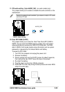
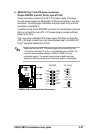
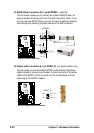
12. GAME/MIDI connector (16-1 pin GAME)
This connector supports a GAME/MIDI module. If your package came
with the optional USB 2.0/GAME module, connect the GAME/MIDI
cable to this connector. The GAME/MIDI port on the module connects
a joystick or a game pad for playing games, and MIDI devices for
playing or editing audio files.
P4B533
®
P4B533 Game Connector
GAME
1
+5V
J2B1
J2CX
MIDI_OUT
J2CY
J2B2
MIDI_IN
J1B1
J1CX
GND
GND
J1CY
J1B2
+5V
9
8
16
+5V