


ASUS P4B533-X motherboard user guide
1-21
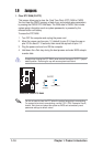
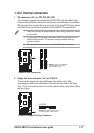
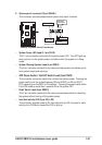
• System Power LED Lead (3-1 pin PLED)
This 3-1 pin connector connects to the system power LED. The LED lights up
when you turn on the system power, and blinks when the system is in sleep
mode.
• System Warning Speaker Lead (4-pin SPKR)
This 4-pin connector connects to the case-mounted speaker and allows you to
hear system beeps and warnings.
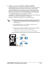
• ATX Power Switch / Soft-Off Switch Lead (2-pin PWR)
This connector connects a switch that controls the system power. Pressing the
power switch turns the system between ON and SLEEP, or ON and SOFT
OFF, depending on the BIOS or OS settings. Pressing the power switch while
in the ON mode for more than 4 seconds turns the system OFF.
• Reset Switch Lead (2-pin RESET)
This 2-pin connector connects to the case-mounted reset switch for rebooting
the system without turning off the system power.
• Hard disk activity LED (2-pin IDE_LED)
This connector supplies power to the hard disk activity LED. Any read or write
activity of an IDE device cause this LED to light up.
P4B533-X
®
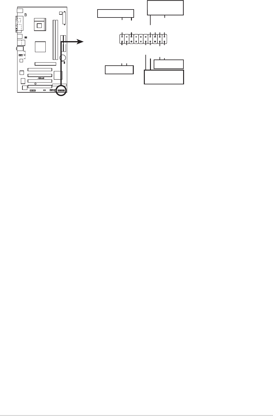
P4B533-X System Panel Connectors
* Requires an ATX power supply
.
PLED-
PWR
+5V
Speaker
Speaker
Connector
Power LED
Ground
Reset SW
Ground
Reset
Ground
Ground
ATX Power
Switch*
PLED+
IDE_LED-
IDE_LED+
IDE_LED
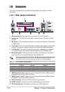
9. System panel connector (20-pin PANEL)
This connector accommodates several system front panel functions.