


ASUS P4C800 Deluxe motherboard user guide
2-21
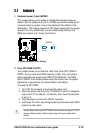
2.8 Connectors
This section describes and illustrates the internal connectors on the
motherboard.
Always connect ribbon cables with the red stripe to Pin 1 on the
connectors. Pin 1 is usually on the side closest to the power connector
on hard drives and CD-ROM drives, but may be on the opposite side
on floppy disk drives.
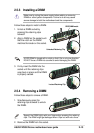
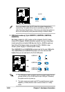
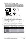
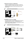
1. Floppy disk drive connector (34-1 pin FLOPPY)
This connector supports the provided floppy drive ribbon cable. After
connecting one end to the motherboard, connect the other end to the
floppy drive. (Pin 5 is removed to prevent incorrect insertion when
using ribbon cables with pin 5 plug).
P4C800
®
NOTE: Orient the red markings on
the floppy ribbon cable to PIN 1.
P4C800 Floppy Disk Drive Connector
PIN 1
FLOPPY
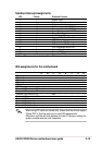
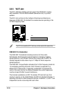
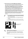
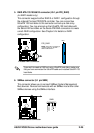
4. SMB2.0 (two 2-pin SMB20)
These jumpers allow you to enable or disable the SMBus 2.0 feature
supported on the motherboard. By default, these jumpers are shorted
(jumper caps on) to disable the feature. If you wish to install PCI
devices that comply with SMBus 2.0 specification, remove the jumper
caps to enable the SMBus 2.0 feature.
P4C800
®
P4C800 SMB20 Setting
SMB20
SMBDATA_ICH
1
SMBCLK_ICH
SMBDATA_PCI
SMBCLK_PCI