


1-24
Chapter 1: Product introduction
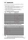
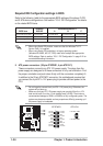
Required IDE Configuration settings in BIOS
Refer to the following table for the appropriate BIOS settings of the above P-ATA
and S-ATA device configurations. See section “2.3.6 IDE Configuration” for details
on the related BIOS items.
Windows Windows 98/Me/NT4.0
BIOS item 2000/XP A B C
Onboard IDE Operate Mode Enhanced Mode Compatible Mode Compatible Mode Compatible Mode
Enhanced Mode Support On S-ATA — — —
IDE Port Settings — Primary P-ATA+S-ATA Sec. P-ATA+S-ATA P-ATA Ports Only
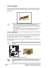
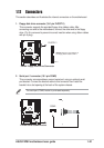
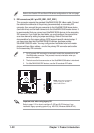
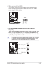
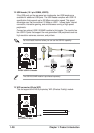
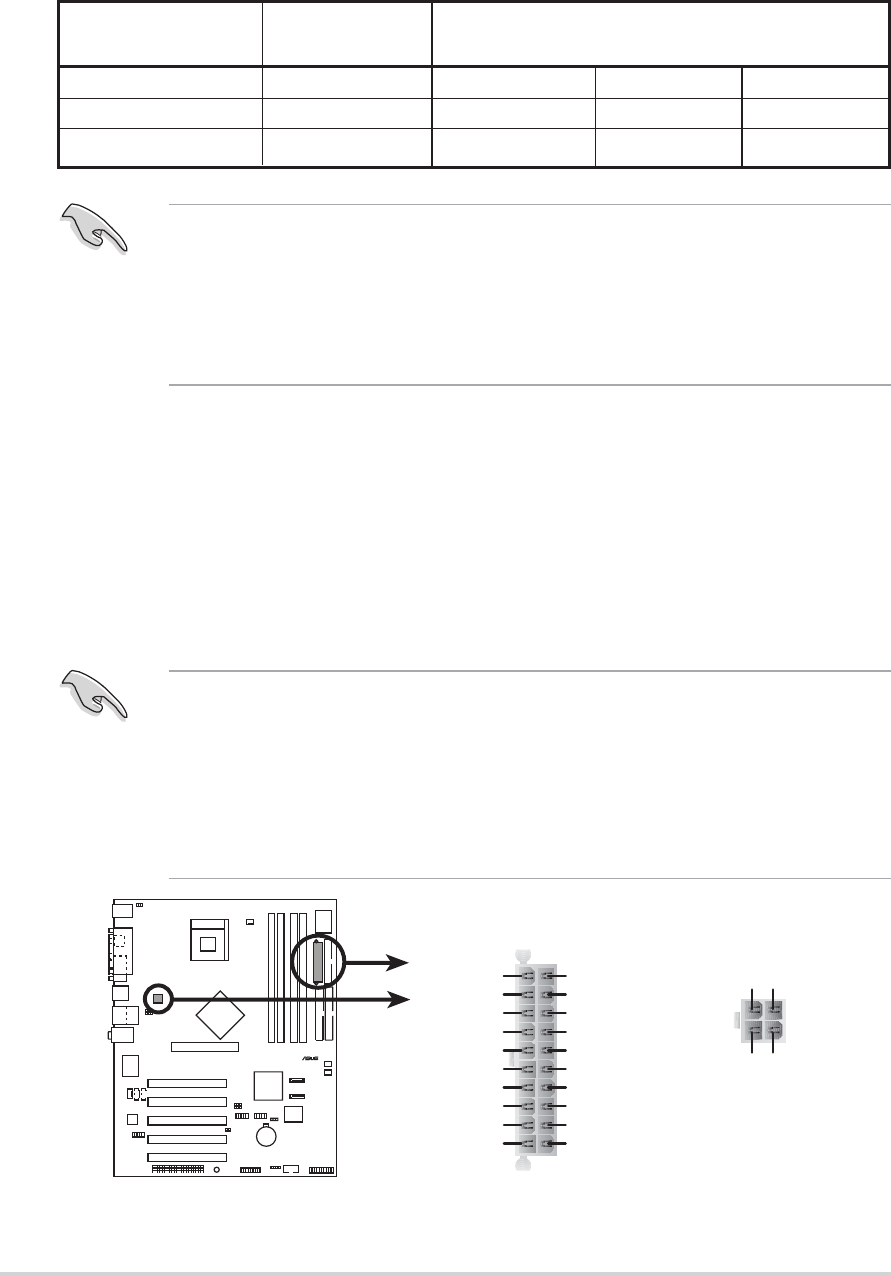
5. ATX power connectors (20-pin ATXPWR1, 4-pin ATX12V1)
These connectors connect to an ATX 12V power supply. The plugs from the
power supply are designed to fit these connectors in only one orientation. Find
the proper orientation and push down firmly until the connectors completely fit.
In addition to the 20-pin ATXPWR1 connector, this motherboard requires that
you connect the 4-pin ATX +12V power plug to provide sufficient power to the
CPU.
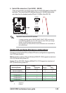
• Do not forget to connect the 4-pin ATX +12V power plug. Otherwise, the
system will not boot up.
• Make sure that your ATX 12V power supply can provide 8A on the +12V
lead and at least 1A on the +5-volt standby lead (+5VSB). The minimum
recommended wattage is 230W, or 300W for a fully configured system. The
system may become unstable and may experience difficulty powering up if
the power supply is inadequate.
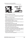
P4P8X
®
P4P8X ATX Power Connector
ATXPWR1 ATX12V1
+3.3VDC
-12.0VDC
COM
PS_ON#
COM
COM
COM
-5.0VDC
+5.0VDC
+5.0VDC
PWR_OK
+12.0VDC
+3.3VDC
+3.3VDC
COM
+5.0VDC
COM
+5.0VDC
COM
+5VSB
+12V DC GND
+12V DC GND
• When using Serial ATA function, make sure that the Windows
®
XP™
Service Pack 1 is installed.
• When using Serial ATA hard disks in a legacy operating system
(Windows 98, 98SE, ME, NT, DOS) make sure to adjust the appropriate
BIOS settings. Refer to section “2.3.6 IDE Configuration” in page 2-12 for
more detailed setting information.