


ASUS P4S533 motherboard user guide
39
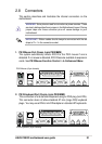
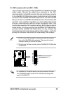
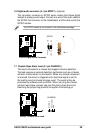
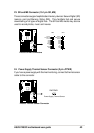
16. Digital audio connector (4-1 pin SPDIF1) (optional)
This connector connects an S/PDIF audio module that allows digital
instead of analog sound output. Connect one end of the audio cable to
the S/PDIF Out connector on the motherboard, and the other end to the
S/PDIF module.
P4S533
®
P4S533 Digital Audio Connector
SPDIF1
GND
+5V
SPDIF_IN
SPDIF_OUT
GND
1
The S/PDIF module is not included in the motherboard package.
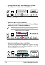
P4S533
®
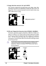
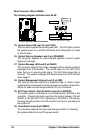
P4S533 Chassis Alarm Lead
CHASSIS1
+5VSB_MB
Chassis Signal
GND
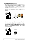
17. Chassis Open Alarm Lead (4-1 pin CHASSIS1)
This lead is intended for a chassis that supports intrusion detection.
The lead requires an external detection mechanism such as a chassis
intrusion monitor/sensor or microswitch. When any chassis component
is removed, the sensor is triggered and a high-level signal is sent to
this lead to record a chassis intrusion event. The event is then be
processed by software such as LDCM. When not using the chassis
intrusion lead, place a jumper cap over the pins to close the circuit.
Removing the jumper cap prevents the system from booting up.