


40
Chapter 2: Hardware information
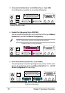
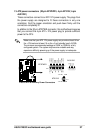
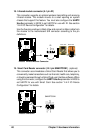
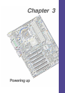
19. Smart Card Reader connector (14-1 pin SMARTCON1) (optional)
This connector accommodates a Smart Card Reader that allows you to
conveniently make transactions such as financial, health care, telephony,
or traveling services through a Smart Card user interface software. When
using this connector, configure the UART2 Use As parameter in BIOS to
set UART2 for use with Smart Card. See section “4.4.2 I/O Device
Configuration” for details.
P4S533
®
P4S533 Smartcard
SMARTCON1
NC
SCPWR
NC
NC
NC2
VCC
GND
SCIO
SCRRES#
NC
SCRCLK
1
NC
SCRREST
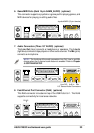
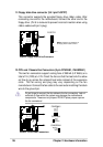
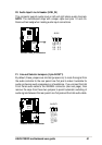
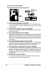
18. Infrared module connector (5-1 pin IR)
This connector supports an optional wireless transmitting and receiving
infrared module. This module mounts to a small opening on system
chassis that support this feature. You must also configure the UART2
Use As parameter in BIOS to set UART2 for use with IR. See section
“4.4.2 I/O Device Configuration” for details.
Use the five pins as shown in Back View and connect a ribbon cable from
the module to the motherboard SIR connector according to the pin
definitions.
P4S533
®
P4S533 Infrared Module Connector
Front View Back View
+5V
IRTX
IRRX
(NC)
GND
+5V
IRRX
IRTX
GND
IR
1