


2-22
Chapter 2: Hardware information
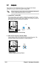
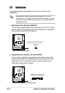
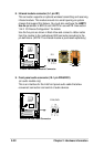
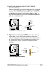
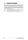
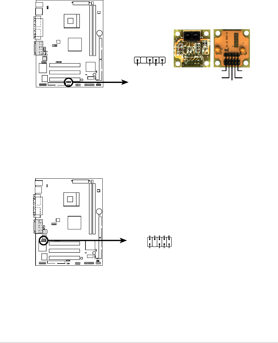
8. Infrared module connector (5-1 pin IR1)
This connector supports an optional wireless transmitting and receiving
infrared module. This module mounts to a small opening on system
chassis that support this feature. You must also configure the UART2
Use As parameter in BIOS to set UART2 for use with IR. See section
“4.4.2 I/O Device Configuration” for details.
Use the five pins as shown in Back View and connect a ribbon cable
from the module to the motherboard SIR connector according to the
pin definitions. (NOTE: The infrared module is purchased separately.)
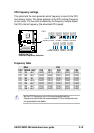
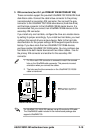
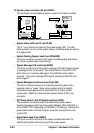
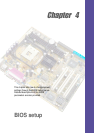
9. Front panel audio connector (10-1 pin FPAUDIO1)
(on audio models only)
This is an interface for the Intel front panel audio cable that allow
convenient connection and control of audio devices.
P4SDR-VM
®
P4SDR-VM Infrared Module Connector
Back View
+5V
IRTX
IRRX
(NC)
GND
Front View
IR1
+5V
IRRX
IRTX
GND
1
P4SDR-VM
®
P4SDR-VM Intel Panel Connector
2
9
10
FPAUDIO1
BOUT_L
MIC2
LOUT_R
LOUT_L
NC
MICPWR+5VA
AGND_A
1
BOUT_R