


2-24
Chapter 2: Hardware information
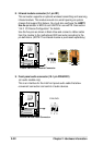
• System Power LED Lead (3-1 pin PLED)
This 3-1 pin connector connects to the system power LED. The LED
lights up when you turn on the system power, and blinks when the system
is in sleep mode.
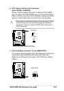
• System Warning Speaker Lead (4-pin SPEAKER)
This 4-pin connector connects to the case-mounted speaker and allows
you to hear system beeps and warnings.
• System Message LED Lead (2-pin MLED)
This 2-pin connector is for the system message LED that indicates receipt
of messages from a fax/modem. The normal status for this LED is ON,
when there is no incoming data signal. The LED blinks when data is
received. The system message LED feature requires an ACPI OS and
driver support.
• System Management Interrupt Lead (2-pin SMI)
This 2-pin connector allows you to manually place the system into a
suspend mode, or “green” mode, where system activity is instantly
decreased to save power and to expand the life of certain system
components. Attach the case-mounted suspend switch to this 2-pin
connector.
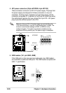
• ATX Power Switch / Soft-Off Switch Lead (2-pin PWR)
This connector connects a switch that controls the system power.
Pressing the power switch turns the system between ON and SLEEP, or
ON and SOFT OFF, depending on the BIOS or OS settings. Pressing the
power switch while in the ON mode for more than 4 seconds turns the
system OFF.
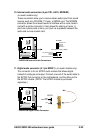
• Reset Switch Lead (2-pin RESET)
This 2-pin connector connects to the case-mounted reset switch for
rebooting the system without turning off the system power.
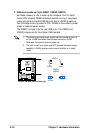
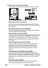
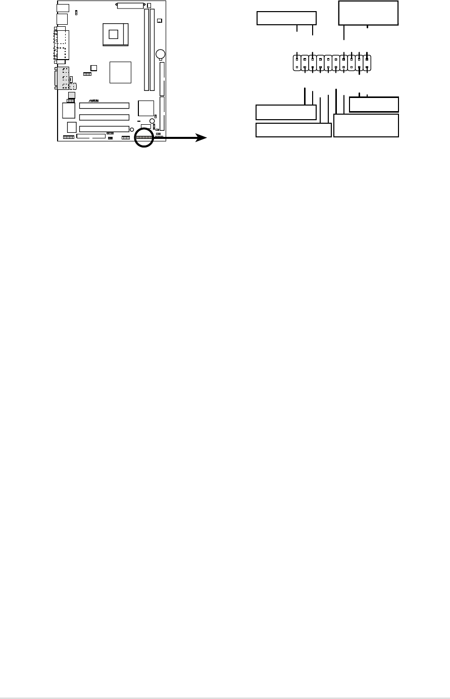
12. System panel connector (20-pin PANEL)
This connector accommodates several system front panel functions.
P4SDR-VM
®
P4SDR-VM System Panel Connectors
*
Requires an ATX power supply.
PLED
Ground
MLED
PWR
+5VSB
+5V
Speaker
Speaker
Connector
Power LED
Ground
+5 V
Reset SW
SMI Lead
Message LED
ExtSMI#
Ground
Reset
Ground
Ground
ATX Power
Switch*