


40 ASUS P4T-F User’s Manual
Connectors
3. H/W SETUP
3. HARDWARE SETUP
P4T-F
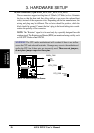
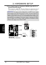
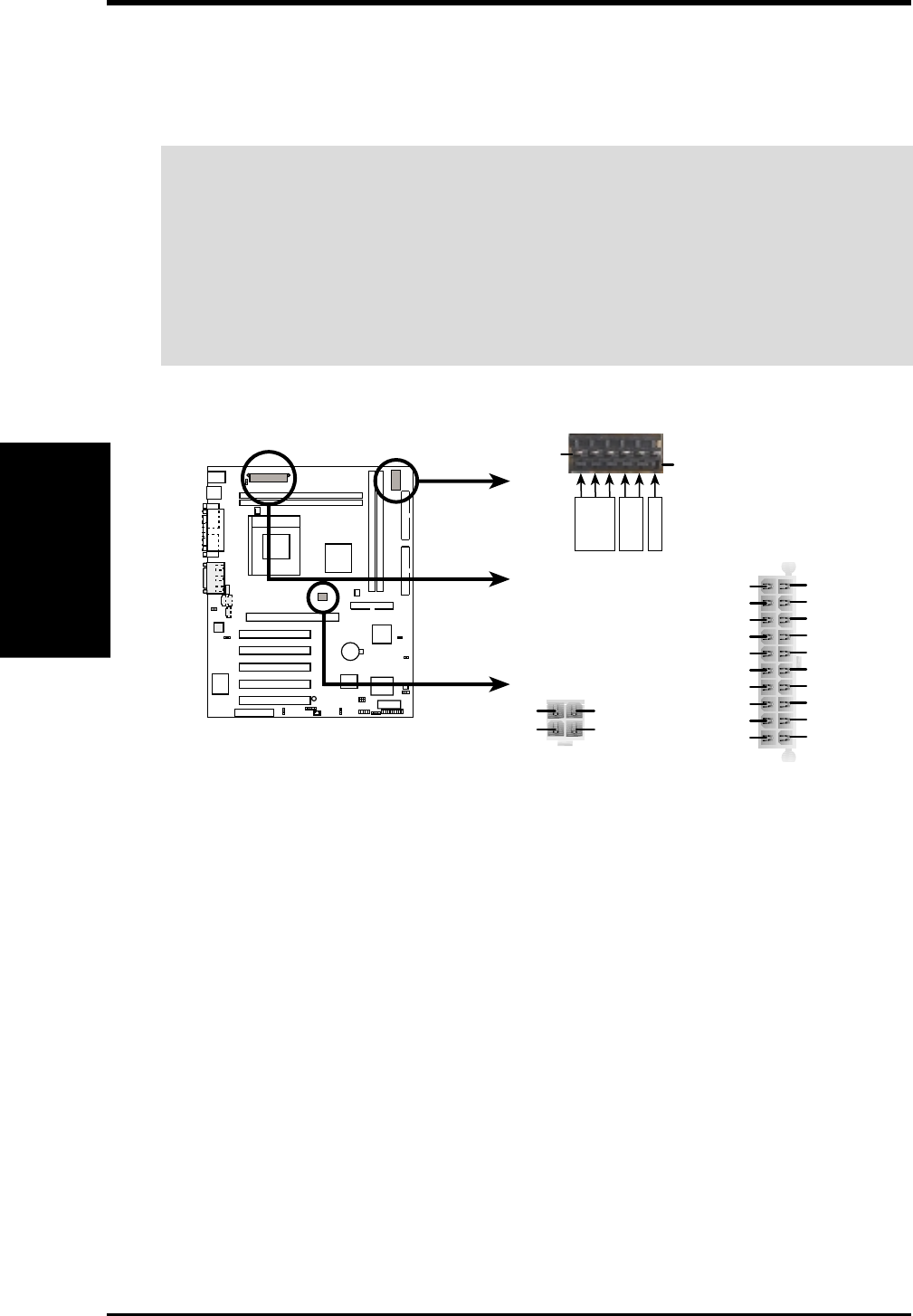
P4T-F ATX &
Auxiliary Power Connectors
ATX12V
ATXPWR
AUXPWR
Pin 1
COM
+3V
+5V
Key
+12V DC
COM
+12V DC
COM
Pin 1
Pin 1
+3.3VDC
-12.0VDC
COM
PS_ON#
COM
COM
COM
-5.0VDC
+5.0VDC
+5.0VDC
PWR_OK
+12.0VDC
+3.3VDC
+3.3VDC
COM
+5.0VDC
COM
+5.0VDC
COM
+5VSB
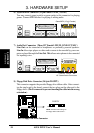
17) Power Supply Connectors (20-pin block ATXPWR) (4-pin ATX12V) (6
pin block AUXPWR (optional)
These connectors supply ATX 12V power. Each power supply plug inserts in
one orientation only. Push down firmly and make sure the pins are aligned.
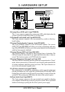
IMPORTANT: For typical system configurations, an ATX12V power supply
that can supply at least 230W and at least 8.5A on the +12V lead is required. For
heavily-loaded configurations, an ATX12V power supply that can supply at least
300W is required. Your system may become unstable/unreliable and may expe-
rience difficulty in powering up if your power supply is inadequate. For Wake-
On-LAN support, your ATX power supply (minimum recommended wattage:
230watts) must supply at least 720mA +5VSB.